Anti-reflux pressurization type filtering device

A filtration device and anti-backflow technology, applied in the direction of filtration and separation, moving filter element filters, separation methods, etc., can solve the problems of increasing the use cost, reverse fluid flow, affecting the filtration capacity of the filter equipment, etc., to reduce the use cost, The effect of avoiding the work of replacing the screw

Pending Publication Date: 2018-12-14
黄得锋
View PDF5 Cites 1 Cited by
  • Summary
  • Abstract
  • Description
  • Claims
  • Application Information

AI Technical Summary

Problems solved by technology

[0002] At present, part of the filter equipment is to introduce the fluid into the filter element by means of continuous pressurization during the filtration process. between the screw depth and the filter element; in order to improve the introduction speed and filtration efficiency of the fluid, multiple sections of screws with different diameters will be installed in the filter element, and the screws with different diameters can pressurize the fluid in turn, which can improve the filtration efficiency and The purpose of filtering effect; the disadvantage of this kind of filtering equipment is: in order to ensure that the fluid will not flow reversely under pressure inside the filter element, the distance between the screw and the rotating interior needs to be controlled within 0.5mm, and the screw will be worn after long-term use phenomenon, the distance between the worn screw and the inner wall of the filter element will increase. At this time, the phenomenon of fluid reverse flow will easily occur, which will affect the filtration capacity of the filter equipment. Therefore, this filter equipment needs to be repaired after a period of use. The operation of replacing the screw increases the cost of use

Method used


Image

  • Anti-reflux pressurization type filtering device
  • Anti-reflux pressurization type filtering device

Examples


Embodiment 1

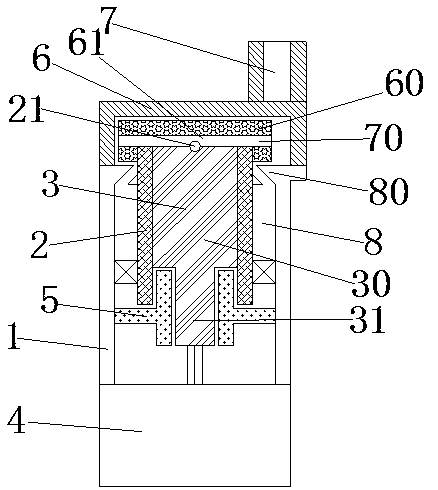
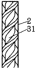
[0017] An anti-backflow pressurized filter device, including a grid cylinder 1, a filter element 2, a screw 3 and a drive motor 4; the screw 3 includes a small screw 30 and a large screw 31, and the diameter of the small screw 30 is smaller than that of the large screw 31 screw diameter, the small screw 30 and the large screw 31 are all arranged inside the filter core 2, and the threaded surface of the large screw 31 is in sealing contact with the inner wall of the filter core 2; the small screw 30 is fixed on one end of the large screw 31, and the other end of the small screw 30 It is connected with the output shaft of the drive motor 4; the filter core 2 is arranged inside the grid cylinder 1, and a bearing 20 is arranged between the filter core 2 and the grid cylinder 1, so that the filter core 2 and the grid cylinder 1 can rotate relatively; A stator cylinder 5 is arranged between the filter element 2 and the small screw rod 30, and the stator cylinder 5 is sealed and conne...


PUM


Abstract

The invention relates to an anti-reflux pressurization type filtering device. The filtering device comprises a grid cylinder, a filter element, screw rods and a driving motor, wherein the screw rods comprise a small screw rod and a big screw rod, the screw diameter of the small screw rod is smaller than that of the big screw rod, the small screw rod and the big screw rod are both arranged inside the filter element, and the thread surface of the big screw rod is in sealing contact with the inner wall surface of the filter element. According to the anti-reflux pressurization type filtering device provided by the invention, as the screw rods comprise the big screw rod and the small screw rod, and the filter element can rotate synchronously with the big screw rod, the small screw rod can rotate relatively to a stator barrel, so that abrasion of the big screw rod can be avoided, the small screw rod is arranged inside the stator barrel, and the filtering effect of the filter element cannot be affected. Compared with the prior art, the anti-reflux pressurization type filtering device provided by the invention overcomes the problem caused by the increasing of the distances between the screw rods and the filter element due to the abrasion of the screw rods, can avoid the operation of regularly replacing the screw rods, and greatly reduces the use cost.

Description

technical field [0001] The invention relates to the field of purification and filtering equipment, in particular to an anti-backflow pressurized filtering device. Background technique [0002] At present, part of the filter equipment is to introduce the fluid into the filter element by means of continuous pressurization during the filtration process. between the screw depth and the filter element; in order to improve the introduction speed and filtration efficiency of the fluid, multiple sections of screws with different diameters will be installed in the filter element, and the screws with different diameters can pressurize the fluid in turn, which can improve the filtration efficiency and The purpose of filtering effect; the disadvantage of this kind of filtering equipment is: in order to ensure that the fluid will not flow reversely under pressure inside the filter element, the distance between the screw and the rotating interior needs to be controlled within 0.5mm, and t...

Claims


Application Information

Patent Timeline
IPC IPC(8): B01D33/11B01D33/76B01D33/80
CPCB01D33/11B01D33/76B01D33/801
Inventor 黄得锋
Owner 黄得锋
Why Eureka
Try Eureka