Folding magnetic type sweeping mop

A magnetic suction and mop technology, applied in the field of sweeping mop, can solve problems such as instability, and achieve the effects of stable device, stable movement, and simple and convenient operation

Pending Publication Date: 2018-12-18
TIANJIN YULONG XINYUAN SCI & TECH CO LTD
View PDF1 Cites 0 Cited by
  • Summary
  • Abstract
  • Description
  • Claims
  • Application Information

AI Technical Summary

Problems solved by technology

[0005] The purpose of the present invention is to provide a folding magnetic mop, which has the advantages of convenient operation and use, can be folded, occupies a small space, and can prevent people or objects from being damaged by unintentional contact. There is still the problem of encountering people or property damage

Method used


Image

  • Folding magnetic type sweeping mop
  • Folding magnetic type sweeping mop
  • Folding magnetic type sweeping mop

Examples


Embodiment 1

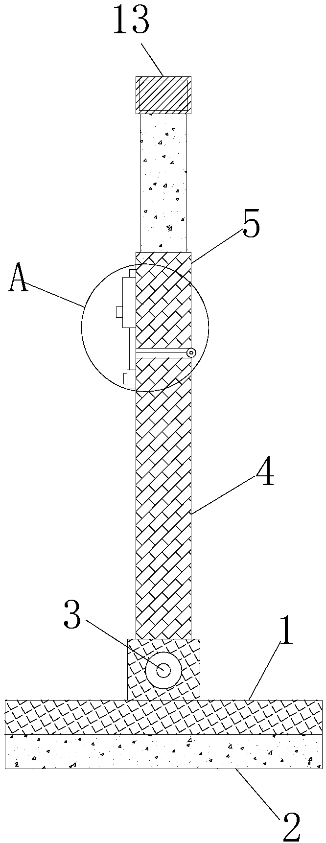
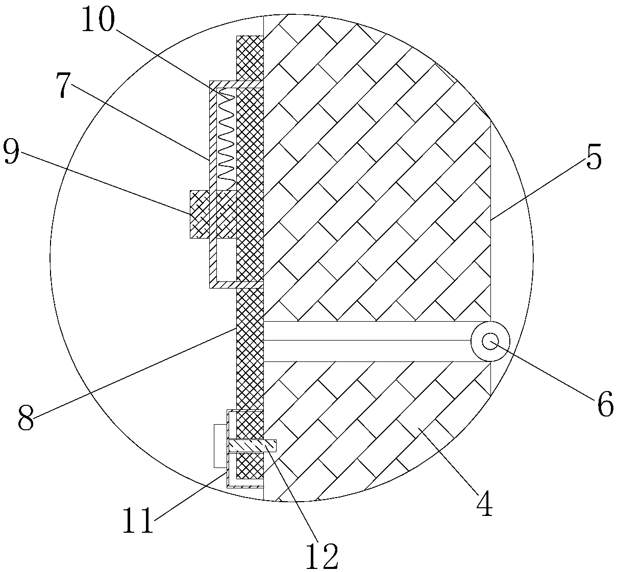
[0023] refer to Figure 1-3 , a folding magnetic mop for sweeping the floor, comprising a mop head 1, mopping cotton 2 is fixed at the bottom of the mop head 1, and a lower mop rod 4 is hinged on the top of the mop head 1 through a rotating pin 3, which is convenient for the use of the mop head 1, To increase the range of mopping the floor, the top of the lower tow bar 4 is hinged with the upper tow bar 5 through the hinge 6, the left bottom of the upper tow bar 5 is fixed with an upper fixed block 7, and the upper left side of the lower tow bar 4 is fixed with a lower fixed block 11, The upper fixed block 7 is provided with a movable plate 8, the top of the movable plate 8 runs through the top wall of the upper fixed block 7, and the bottom end of the movable plate 8 runs through the bottom wall of the upper fixed block 7, the top wall of the lower fixed block 11 and extends into the lower fixed block. In the block 11, the left side of the lower fixed block 11 is fixedly conn...

Embodiment 2

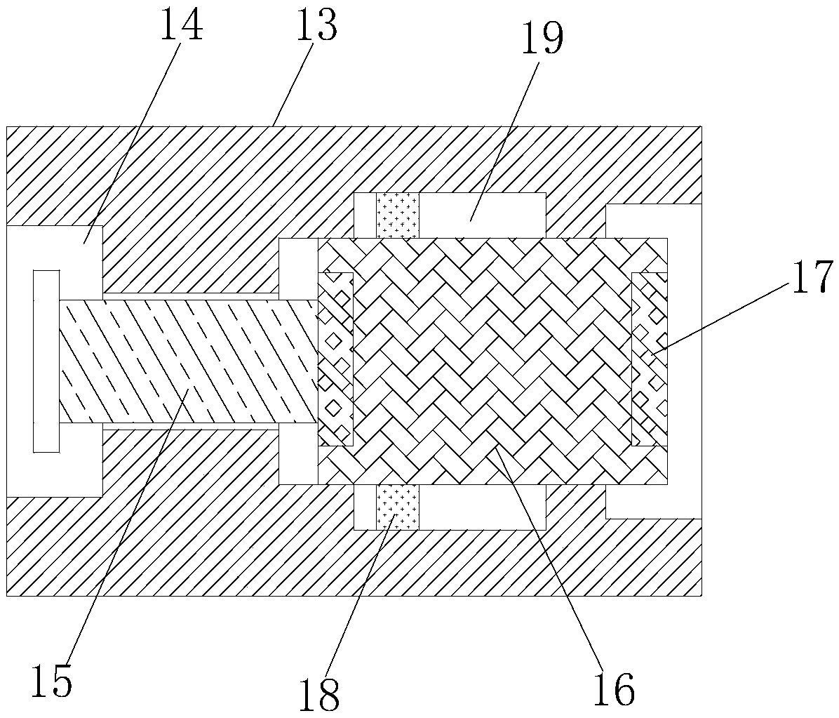
[0027] Such as Figure 4 As shown, this embodiment has the following distinguishing features from Embodiment 1, and also includes a radial groove 20, a wedge block 21, a push rod 22 and a tension spring 23, and the stud 15 is inserted into the through hole through the through hole 14, the tension spring 23 is sleeved on the stud 15, one end of the tension spring 23 is connected to the connection block 16, and the other end of the tension spring 23 is connected to the top Block 13 is connected. The outer end of the stud 15 has a flange.

[0028] The parts of the present invention that are not described in detail are known technologies of those skilled in the art. The radial groove 20 is arranged on the left side of the opening 14, the wedge block 21 is embedded in the radial groove 20, and the lower end of the wedge block 21 is connected with the upper end of the push rod 22, so that The lower end of the push rod 22 passes through the upper tow bar 5 and extends out of the l...


PUM


Abstract

The invention discloses a folding magnetic type sweeping mop. The folding magnetic type sweeping mop includes a mop head, wherein the bottom end of the mop head is fixed with mopping cotton, and the top end of the mop head is hinged with a lower towbar through a rotating pin; the top end of the lower towrod is hinged to an upper towbar by a hinge; an upper fixing block is fixed at the left bottomof the upper towbar; a lower fixing block is fixed at the upper part of the left side of the lower towbar; a moving plate is arranged in the upper fixing block; the top end of the moving plate penetrates the top wall of the upper fixing block; the bottom end of the moving plate penetrates the bottom wall of the upper fixing block and the top wall of the lower fixing block in order and extends intothe lower fixing block; the left side of the lower fixing block is fixedly connected to the moving plate by a fixing bolt; the left upper part of the moving plate is connected and a moving block; a spring is connected to the right side of the top end of the moving block; and the top end of the spring is fixed on the top wall in the upper fixing block. The folding magnetic type sweeping mop has the advantages of being convenient to operate and use, being foldable, occupying small space, and being able to prevent potential risks caused by unconscious touch.

Description

technical field [0001] The invention relates to the technical field of sweeping mops, in particular to a foldable magnetic suction type sweeping mop. Background technique [0002] In current life, there are many types of brooms, including bamboo, wood, plastic and metal. No matter what material they are made of, they all have one characteristic: they are large and immutable, and they are generally leaned against the corner when not in use. If they are accidentally touched, it is easy to cause unnecessary damage to people or things. damage. [0003] After searching, the Chinese patent authorization number CN204016198U discloses a foldable telescopic broom, which comprises a broom head and a broom rod. The mop head is composed of 4 cuboid shapes. sweep the floor. [0004] The existing sweeping mop has the following disadvantages: the operation is cumbersome, the folding effect is average, and the folded mop bars will swing with each other, making the folded unstable and inc...

Claims


Application Information

Patent Timeline
IPC IPC(8): A47L13/20A47L13/42B25G1/04
CPCA47L13/20A47L13/42B25G1/04
Inventor 陆爱军
Owner TIANJIN YULONG XINYUAN SCI & TECH CO LTD
Why Eureka
Try Eureka