
Automatic bearing cleaning machine

A technology for automatic cleaning machines and bearings, which is applied to dryers, cleaning methods and tools, and cleaning methods using liquids, etc., which can solve the problems of poor cleaning of bearings, waiting for shutdown, and low processing efficiency.

Inactive Publication Date: 2018-12-18
陈荣乾
View PDF8 Cites 2 Cited by
  • Summary
  • Abstract
  • Description
  • Claims
  • Application Information

AI Technical Summary

Problems solved by technology

The cleaning of the inner and outer rings of existing bearings requires separate loading and unloading operations, that is, it needs to stop and wait during the loading and unloading process, and the processing efficiency is low
And because ultrasonic immersion and high-pressure spray cleaning have their own advantages and disadvantages, the use of a single ultrasonic immersion and high-pressure spray cleaning method has the problem of poor cleaning of the bearing. After cleaning, the bearing needs to be taken out for drying operation, and the degree of automation of processing is low.

Method used


Image

  • Automatic bearing cleaning machine
  • Automatic bearing cleaning machine
  • Automatic bearing cleaning machine

Examples


Embodiment 1

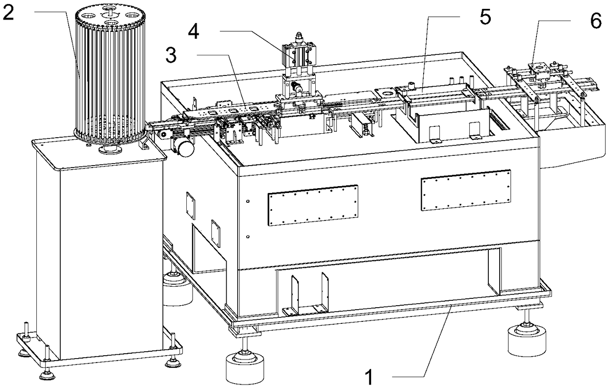
[0025] Such as Figure 1-Figure 12 The shown automatic bearing cleaning machine includes a frame 1 and a feeding system 2 on it, a material pushing system 3 , a bearing cleaning system 4 , an ultrasonic cleaner 5 , and a drying system 6 .

[0026] The feeding system 2 is connected with the pushing system 3, the positions of the bearing cleaning system 4, the ultrasonic cleaner 5 and the drying system 6 correspond to the pushing system 3, and the pushing system 3 sequentially drives the bearing through the bearing cleaning system 4, the ultrasonic cleaner 5 and the Blow dry the bearing movement on the system 6. The bearing cleaning system 4 completes the high-pressure cleaning of the bearings; the ultrasonic cleaner 5 completes the ultrasonic cleaning of the bearings; the drying system 6 dries the liquid on the bearings.

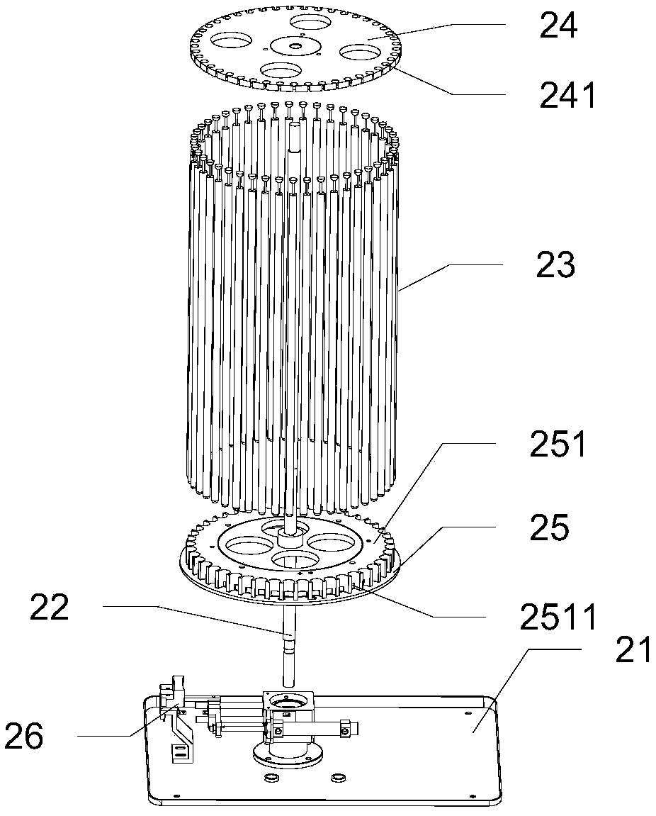
[0027] The feeding system 2 includes a placement disc 21, a rotating shaft 22, a sleeve rod 23, an upper rotating disc 24, a lower rotating disc 25, a push ...

Embodiment 2

[0046] Such as figure 1 , figure 2 , image 3 , Figure 4 , Figure 5 , Figure 6 , Figure 7 , Figure 8 , Figure 12 , Figure 13 , Figure 14 and Figure 15 The shown automatic bearing cleaning machine includes a frame 1 and a feeding system 2 on it, a material pushing system 3 , an outer wheel cleaning system 9 , an ultrasonic cleaner 5 , and a drying system 6 .

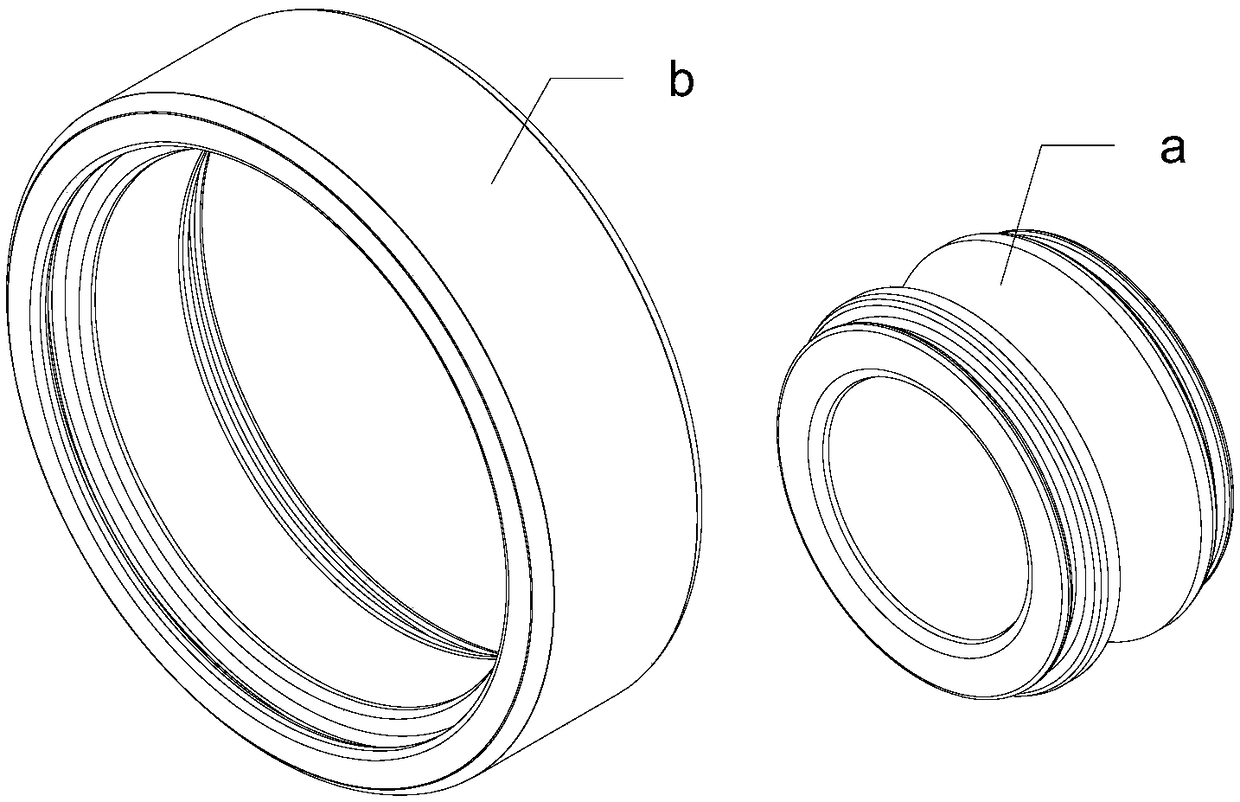
[0047] The difference between this embodiment and Embodiment 1 is that the bearing cleaning system 4 is different, and other structures are the same as Embodiment 1. The bearing cleaning machine of this embodiment is more suitable for cleaning the outer wheel b.

[0048] The bearing cleaning system 4 includes a third lifting cylinder 91 , an outer wheel cleaning device 92 and an outer wheel cleaning seat 93 . The third lifting cylinder 91 is installed on the frame 1 through the cylinder base, the third lifting cylinder 91 is connected to the outer wheel cleaning device 92 through the connecting frame...


PUM


Abstract

The invention relates to the field of automatic cleaning equipment, and discloses an automatic bearing cleaning machine. The automatic bearing cleaning machine comprises a machine frame, and a feed system and a material pushing system arranged on the machine frame. The feed system is connected with the material pushing system. The feed system comprises a placing disc, a rotating shaft, a loop bar,an upper rotating disc, a lower rotating disc, a push rod device and a first motor. The automatic bearing cleaning machine has the advantages that bearing feed, high pressure spraying cleaning, ultrasonic immersion cleaning and drying can be completed automatically, bearing cleanliness is excellent, and processing efficiency is high.

Description

technical field [0001] The invention relates to the field of automatic cleaning equipment, in particular to automatic cleaning equipment for bearings. Background technique [0002] Bearings are mainly assembled from inner and outer rings. The current bearing cleaning is mainly aimed at cleaning the assembled bearings of the inner and outer rings. The cleaning methods are ultrasonic immersion and high-pressure spraying. One of two ways. The cleaning of the inner wheel and the outer wheel of the existing bearing requires separate loading and unloading operations, that is, it needs to stop and wait during the loading and unloading process, and the processing efficiency is low. And because ultrasonic immersion and high-pressure spray cleaning have their own advantages and disadvantages, the use of a single ultrasonic immersion and high-pressure spray cleaning method has the problem of poor cleaning of the bearing. After cleaning, the bearing needs to be taken out for drying ope...

Claims


Application Information

Patent Timeline
IPC IPC(8): B08B3/12B08B3/02B08B13/00F26B21/00
CPCB08B3/02B08B3/12B08B13/00F26B21/00
Inventor 陈荣乾
Owner 陈荣乾
Learn More