Gripper base for vertical machine tools

A technology of using a gripper seat and a machine tool, which is applied in the field of CNC machine tools, can solve the problems of inability to meet processing requirements and structural limitations of the gripper seat, and achieve the effects of simple structure, low manufacturing cost and convenient operation.

Active Publication Date: 2020-11-03
太原重工轨道交通设备有限公司
View PDF9 Cites 0 Cited by
  • Summary
  • Abstract
  • Description
  • Claims
  • Application Information

AI Technical Summary

Problems solved by technology

[0004] When the processed product is a high-precision wheel ring with a wheel diameter less than 800mm, the "L"-shaped jaw seat cannot meet the processing requirements due to structural limitations.

Method used


Image

  • Gripper base for vertical machine tools
  • Gripper base for vertical machine tools
  • Gripper base for vertical machine tools

Examples


Embodiment Construction

[0030] In order to make the purpose, technical solution and advantages of the present invention clearer, the technical solution of the present invention will be clearly and completely described below in conjunction with specific embodiments of the present invention and corresponding drawings. Apparently, the described embodiments are only some of the embodiments of the present invention, but not all of them. Based on the embodiments of the present invention, all other embodiments obtained by persons of ordinary skill in the art without making creative efforts fall within the protection scope of the present invention.

[0031] The technical solutions provided by the embodiments of the present invention will be described in detail below in conjunction with the accompanying drawings.

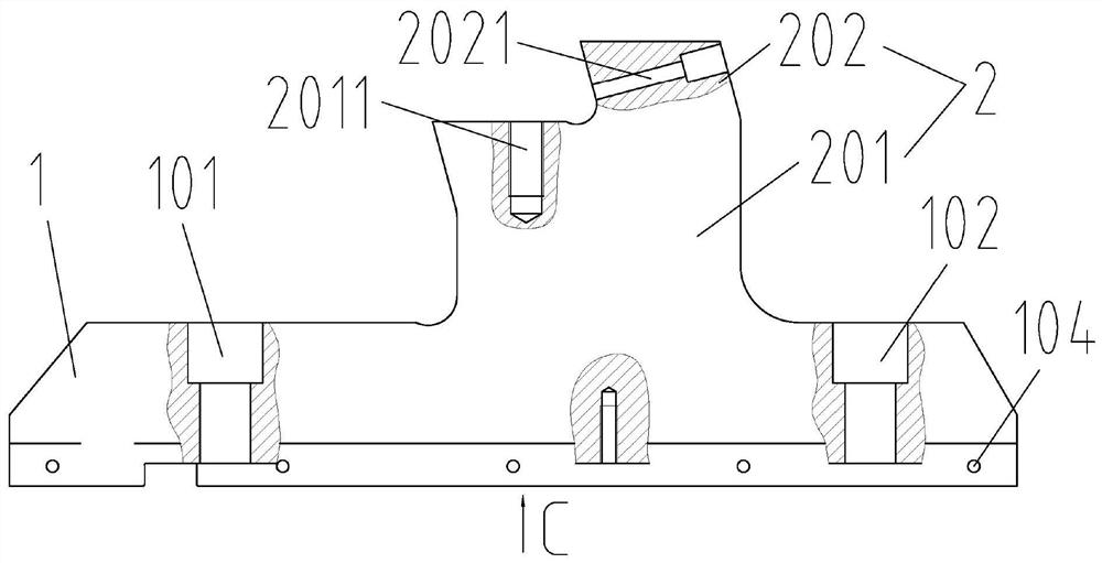
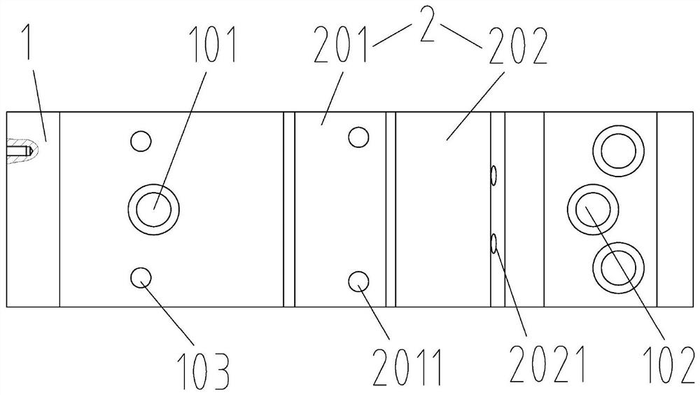
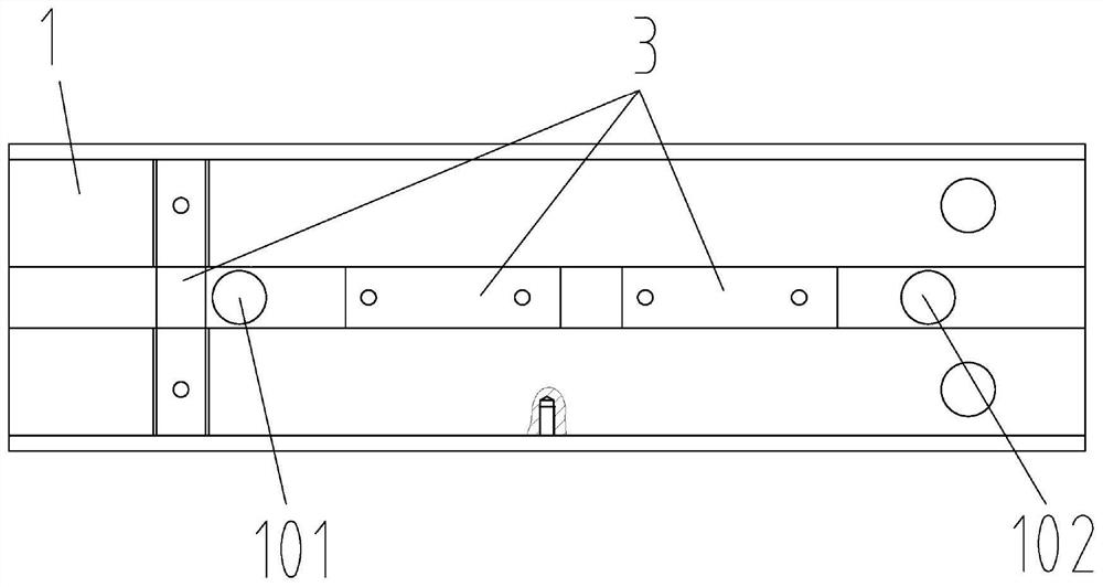
[0032] As shown in the drawings, the embodiment of the present invention provides a jaw base for vertical machine tools. The jaw base for vertical machine tools in this embodiment includes a base 1...


PUM


Abstract

The invention discloses a clamping jaw base for a vertical machine tool. The clamping jaw base for the vertical machine tool comprises a base and a clamping jaw head fixing table; the clamping jaw head fixing table is arranged on the upper end surface of the base for mounting and positioning a tread clamping jaw head and a rim clamping jaw head; the lower end surface of the base is contacted and matched with a machine tool worktable; a first positioning through hole and a second positioning through hole perpendicular to the upper end surface of the base are arranged on the upper end surface ofthe base on two sides of the clamping jaw head fixing table; and the first positioning through hole and the second positioning through hole are used for positioning the clamping jaw base for the vertical machine tool and the machine tool worktable. The clamping jaw base for the vertical machine tool is provided with the positioning through holes for positioning the clamping jaw base on the end surfaces of the base on two sides of the clamping jaw head fixing base, so that the clamping base is larger in moving space to the circle center direction of the worktable on the machine tool worktable,and the size range of workpieces fixed by the clamping jaw base is wider; and the clamping jaw base for the vertical machine tool is simple in structure, convenient to operate and low in production cost.

Description

technical field [0001] The invention relates to the technical field of numerical control machine tools, in particular to a jaw seat for a vertical machine tool. Background technique [0002] The clamping jaws of the existing vertical machine tools are in the form of an "L" structure, which is mainly used for clamping and processing of domestic and foreign railways, urban rails, locomotives and wheel rings of motor vehicles. The existing clamping jaws can clamp The diameter range of the wheel holding ring is approximately 800mm-1250mm. [0003] The inventor finds that the prior art has at least the following problems: [0004] When the processed product is a high-precision wheel ring with a wheel diameter less than 800mm, the "L"-shaped jaw seat cannot meet the processing requirements due to structural limitations. Contents of the invention [0005] In order to solve the above-mentioned technical problems in the prior art, the present invention provides a jaw seat for a v...

Claims


Application Information

Patent Timeline
Patent Type & Authority Patents(China)
IPC IPC(8): B23Q3/06
CPCB23Q3/06
Inventor 刘果青张治祺李树林魏华成卫二波张磊李志远
Owner 太原重工轨道交通设备有限公司
Why Eureka
Try Eureka