

Concentric-square-shaped cooling device for injection mold
A technology of cooling device and injection mold, which is applied in the field of moulds, can solve the problem of not setting the first and second cooling tanks, the constant cooling water temperature in the cooling water tank, and the inability to improve the stability of the product temperature in the mold. In order to improve the cooling efficiency, shorten the cooling cycle, increase the amount of deformation and thermal stress
- Summary
- Abstract
- Description
- Claims
- Application Information
AI Technical Summary
Problems solved by technology
Method used
Image

Examples
Embodiment Construction
[0028] The invention provides a kind of technical scheme:
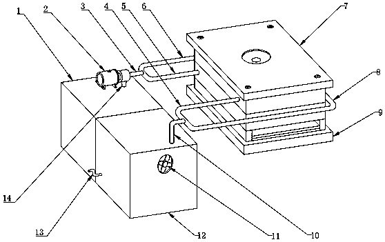
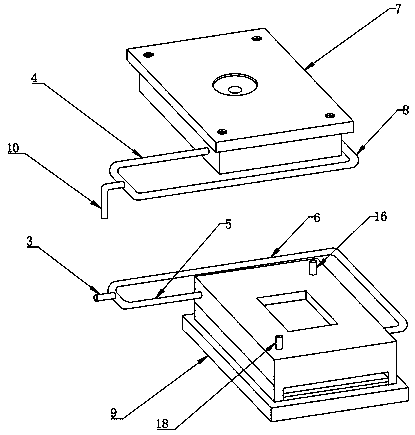
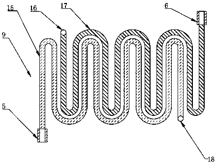
[0029] see Figure 1~6 , a return-type cooling device for injection molds, including a cooling water tank 1, a cooling water tank 12 is arranged on the front side of the cooling water tank 1, a water pump 2 is installed on the top of the cooling water tank 1, and one end of the water pump 2 is connected to a main water inlet pipe 3. One side of the bottom end of the water pump 2 runs through the top of the cooling water tank 1 and is connected with a suction pipe 14. Connected with the second water inlet branch pipe 6, one end of the first water inlet branch pipe 5 and the second water inlet branch pipe 6 is connected with a fixed mold 9, the top of the fixed mold 9 is connected with the movable mold 7, and the front side of one end of the movable mold 7 A first backwater branch pipe 4 is connected, a second backwater branch pipe 8 is connected to the rear side of the other end of the movable mold 7, and one end of t...
PUM
 Abstract
Description
Claims
Application Information