Ink filling machine

An ink filling machine and ink filling technology, applied in the field of ink filling machines, can solve the problems of reducing ink filling efficiency of ink cartridges, high friction between ink filling needles and ink cartridges, etc., and achieve the effects of increasing ink filling efficiency, increasing efficiency, and accelerating speed

Active Publication Date: 2018-12-18
SPEED INFOTECH (BEIHAI) COMPANY LIMITED
View PDF9 Cites 0 Cited by
  • Summary
  • Abstract
  • Description
  • Claims
  • Application Information

AI Technical Summary

Problems solved by technology

[0003] After the upper cover of the ink cartridge is assembled, the device needs to start filling the assembled ink cartridge; during the ink filling process, since the ink filling hole on the ink box is only slightly larger than the ink filling needle, after the ink filling is completed, take out the ink filling needle. Among them, the friction between the ink filling needle and the ink cartridge is relatively large, and there is a possibility that the ink filling needle may lift the ink cartridge, and it is difficult for the ink cartridge to continue to move to the subsequent station. The user needs to remove the ink cartridge from the ink filling needle, which lowers the ink cartridge. Ink filling efficiency

Method used


Image

  • Ink filling machine
  • Ink filling machine
  • Ink filling machine

Examples


Embodiment Construction

[0040] In order to more clearly illustrate the embodiments of the present invention or the technical solutions in the prior art, the specific implementation manners of the present invention will be described below with reference to the accompanying drawings. Obviously, the accompanying drawings in the following description are only some embodiments of the present invention, and those skilled in the art can obtain other accompanying drawings based on these drawings and obtain other implementations.

[0041] In order to make the drawing concise, each drawing only schematically shows the parts related to the present invention, and they do not represent the actual structure of the product. In addition, to make the drawings concise and easy to understand, in some drawings, only one of the components having the same structure or function is schematically shown, or only one of them is marked. Herein, "a" not only means "only one", but also means "more than one".

[0042]According t...


PUM


Abstract

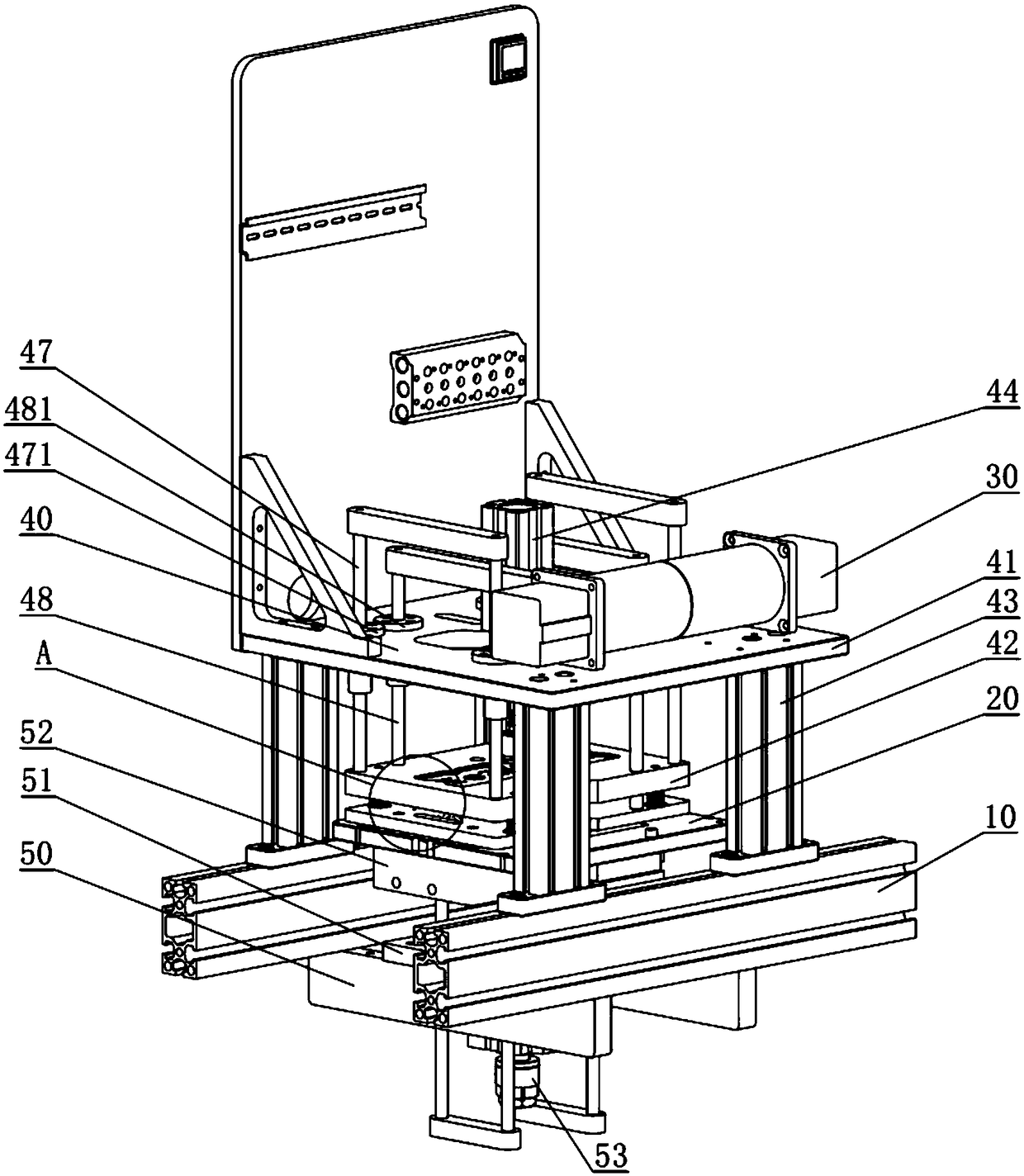
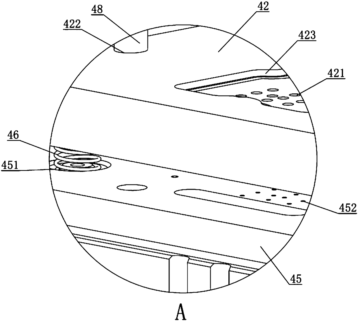
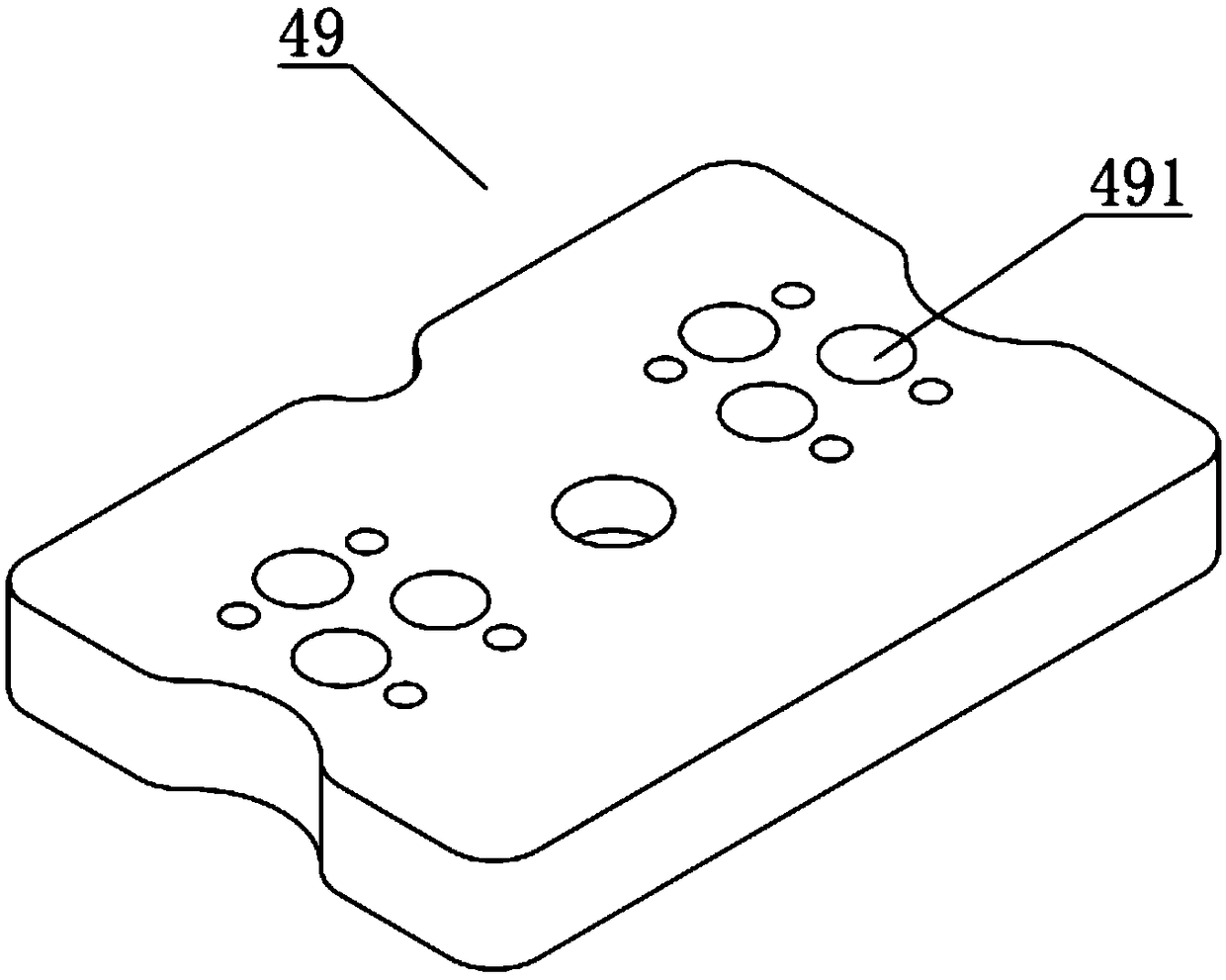
The invention discloses an ink filling machine, and relates to the field of ink cartridge regeneration. The ink filling machine comprises an upper cover component, a lower cover component and an ink filling component which are arranged on a bracket; the lower cover component comprises a lower fixed plate arranged on the bracket, and the lower fixed plate is provided with a lower cover plate used for installing an ink cartridge; the lower fixed plate is further provided with a lower driving device used for regulating the height of the lower cover plate, and the upper cover component comprises an upper fixed plate arranged on the bracket; the upper fixed plate is provided with an upper cover plate, and the upper cover plate is provided with a plurality of upper cover pinholes used for ink filling needles to penetrate; the upper fixed plate is further provided with an upper driving device used for regulating the height of the upper cover plate; the side, far away from the upper fixed plate, of the upper cover plate is further provided with a limit plate, and a limit rod is connected to the upper cover plate through an elastic part; and the limit plate is further provided with a plurality of limit pinholes for the ink filling needles to penetrate. The function of taking out the ink filling needles from the ink cartridge is achieved, and the secondary control of users is not required; and the ink filling process can be performed continuously, and the ink filling efficiency of the ink cartridge is improved.

Description

technical field [0001] The invention relates to the field of regenerating ink cartridges, in particular to an ink filling machine. Background technique [0002] Modern ink cartridges mainly refer to the components used to store printing ink in inkjet printers and finally complete printing. The processing steps of the ink cartridges all adopt automatic processing methods. Modern ink cartridges are mainly composed of a shell, a cover and an internal sponge. After the sponge is loaded into the shell, the automated production line needs to cover the cover on the shell to complete the ink cartridge. assembly. [0003] After the upper cover of the ink cartridge is assembled, the device needs to start filling the assembled ink cartridge; during the ink filling process, since the ink filling hole on the ink box is only slightly larger than the ink filling needle, after the ink filling is completed, take out the ink filling needle. Among them, the friction between the ink filling n...

Claims


Application Information

Patent Timeline
Patent Type & Authority Applications(China)
IPC IPC(8): B41J2/175
CPCB41J2/17506Y02E60/10
Inventor 赵晨海
Owner SPEED INFOTECH (BEIHAI) COMPANY LIMITED
Why Eureka
Try Eureka