Wool fabric knitting machine traction device

A traction device and knitting machine technology, which is applied in the directions of knitting, weft knitting, textile and paper making, etc., can solve the problems of poor overall fixation, poor convenience, and no quick fix connection function.

Active Publication Date: 2018-12-18
汕头市澄海区瑞胜毛织有限公司
View PDF8 Cites 0 Cited by
  • Summary
  • Abstract
  • Description
  • Claims
  • Application Information

AI Technical Summary

Problems solved by technology

[0010] The present invention provides a pulling device for a wool fabric knitting machine through improvement. When overhauling the interior of the internal main body, the take-up reel and the drawing reel are disassembled, and the cover plate is repaired by holding the handle by unscrewing the knobs at the left and right ends of the top of the main body. Pull out, and pull out the support plate in the card slot by the lifting slot, the support plate can touch the ground, and the user can repair or position the equipment in the main body. After the work is completed, cover the cover plate and screw the knob in. The screw holes are tightened to complete the inspection or maintenance work, which is fast and convenient, thus solving the problem of poor convenience and low efficiency when a large number of accessories need to be disassembled when inspecting the interior of the internal main body; The connecting rod in the mechanism is pulled out from the groove in the fixed rod, and the elastic buckle provided on the left end of the front end of the connecting rod is fixed in the clamping hole. There are two groups of clamping holes, which can be adjusted according to the demand. Which group of card holes is convenient for length adjustment, and then the controller starts the electromagnet, and the electromagnet generates adsorption force, which can adsorb the braided conveying equipment or some steel equipment, with strong stability and firmness, thus solving the problem during installation. , the overall fixation is poor, and there is no problem of fast fixed connection function; when the height of the take-up reel and the traction reel needs to be adjusted, the controller starts the second motor to start working, and the output shaft at the bottom of the second motor drives the screw to carry out Turn, the screw rod and the slider in the middle of the outer diameter surface of the slider slide, and the slider can make the first motor slide up and down, and the front ends of the first transmission shaft and the second transmission shaft can slide in the through groove. The back of the two drive shafts can slide with the lifting mechanism in the slide rail through the fixing parts, and the stability is strong when sliding, without shaking, which solves the problem that the take-up reel and the traction reel cannot be adjusted up and down, and cannot be used for traction work at various angles Problem: After long-term work, the first drive shaft and the second drive shaft need to be lubricated. A lubricating mechanism is provided at the front end of the outer diameter surface of the first drive shaft and the second drive shaft. Open the sealing cover on the lubricating sleeve and lubricate The oil is injected from the oil injection port, and the built-in oil-absorbing cotton absorbs it, and then tightens the sealing cover. When the first transmission shaft and the second transmission shaft rotate, the lubricating oil will continue to flow out from the filter holes on the steel ring, and the lubrication will last for a long time. The effect is good, greatly reducing the number of refueling, and solving the problem of manual lubrication of the internal transmission shaft, which consumes manpower and has low lubrication time.

Method used


Image

  • Wool fabric knitting machine traction device
  • Wool fabric knitting machine traction device
  • Wool fabric knitting machine traction device

Examples


Embodiment Construction

[0055] The following will be combined with Figure 1-8 The present invention is described in detail, and the technical solutions in the embodiments of the present invention are clearly and completely described. Apparently, the described embodiments are only some of the embodiments of the present invention, not all of them. Based on the embodiments of the present invention, all other embodiments obtained by persons of ordinary skill in the art without making creative efforts belong to the protection scope of the present invention.

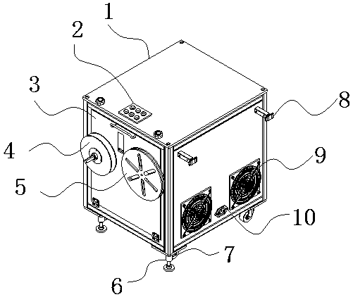
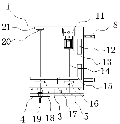
[0056] The present invention provides a pulling device for a wool knitting machine through improvement, including a main body 1, a controller 2, a take-up reel 4, a traction reel 5, a support seat 6, a roller 7, an exhaust window 9, a power interface 10, and a fan 12. The first motor 13, the first transmission shaft 14, the first pulley 15, the belt 17, the second pulley 18, the second transmission shaft 19, the fixing part 20, the slide rail 21, th...


PUM


Abstract

The invention discloses a wool fabric knitting machine traction device. The device comprises a main body, a controller, a take-up reel, a traction plate, a support base, a roller, an exhaust window, apower source interface, a fan, a first motor, a first transmission shaft, a first belt pulley, a belt, a second belt pulley, a second transmission shaft, a fixing member, a slide rail, a pull-out mechanism, a connection mechanism, a lifting mechanism and a lubrication mechanism, when the interior of the internal main body is inspected, the take-up reel and the traction plate are disassembled, byunscrewing knobs at the left and right ends of the top of the main body, a cover plate is pulled out by grabbing a handle by hand, a support plate is pulled out from a clamping slot by a lifting slot,the support plate can contact the ground, a user can examine and repair internal equipment in the main body or move the position, after the work is completed, the cover plate is closed, the knobs arescrewed into screw holes and tightened, and the examine and repair or maintaining work is completed, which is quick and convenient, thereby solving the problems that a large number of accessories need to be disassembled when the interior of the main body is examined and repaired, the convenience is poor, and the efficiency is low.

Description

technical field [0001] The invention relates to the relevant field of knitting equipment accessories, in particular to a pulling device for a wool knitting machine. Background technique [0002] The types of raw materials applicable to the knitting machine are: nylon multifilament (thread), polypropylene filament (thread), polypropylene, polyester, nylon, PP, low-elasticity, high-elasticity, cotton yarn (thread), pearl light, leather, mixed and other high-speed Zouma knitting machine has a complete set of N-color automatic switching devices, and is driven by a computer-controlled motor to automatically switch between yarn feeders, making multi-color pattern knitting simple and easy, and its high-performance weaving action , it is easy to complete the high-quality pattern weaving that can only be completed on large-scale computerized knitting machines. For the miniaturization of high-end computerized knitting, the pulling device of the knitting machine is a device that pulls ...

Claims


Application Information

Patent Timeline
Patent Type & Authority Applications(China)
IPC IPC(8): D04B15/88D04B15/38D04B35/28
CPCD04B15/38D04B15/88D04B35/28
Inventor 蔡道桂
Owner 汕头市澄海区瑞胜毛织有限公司
Why Eureka
Try Eureka