Assembled fan room

A prefabricated, fan technology, applied in ventilation systems, heating methods, space heating and ventilation, etc., can solve the problems of inflexible construction, inability to mass production and use, and achieve the goal of reducing construction pollution, flexible design, and saving resources and energy. Effect

Active Publication Date: 2020-10-16
CHONGQING ERAN ELECTROMECHANICAL EQUIP ENG CO LTD
View PDF9 Cites 0 Cited by
  • Summary
  • Abstract
  • Description
  • Claims
  • Application Information

AI Technical Summary

Problems solved by technology

[0005] The present invention intends to provide a prefabricated fan room to solve the problem that the existing fan room adopts a civil structure, the construction is not flexible enough, and it cannot be mass-produced and used

Method used


Image

  • Assembled fan room
  • Assembled fan room

Examples


Embodiment 1

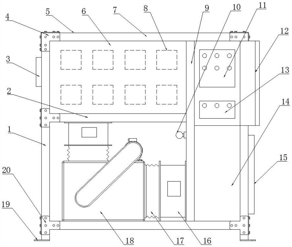
[0027] Embodiment 1 is basically as attached figure 1Shown: Assembled fan room, including the room body, the room body includes a plurality of columns 1, beams 7 and sealing plates 5 that are detachably connected to each other, there are four columns 1, eight beams 7, and five sealing plates 5 They are connected together to form a square room body with a front opening. The room is divided into a working chamber and a control chamber by a vertical partition 9, and a horizontal partition is arranged in the working chamber, and the vertical partition 9 and the horizontal partition all include two side-by-side support beams 2 and are fixed on two supporting beams. Support plate between beams 2. One end of the supporting beam 2 is provided with a stepped surface, and on the stepped surface, a plurality of slots are distributed along the length direction of the supporting beam 2. A supporting rod is bridged between the slots of the two supporting beams 2, and the supporting plate p...

Embodiment 2

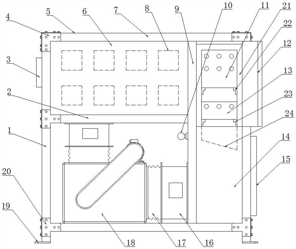
[0030] Embodiment 2, basically as figure 2 As shown, the difference between this embodiment and Embodiment 1 is that a cooling mechanism is provided on the inner wall of the upper part of the control chamber, and the strong current control cabinet 11 and the weak current control cabinet 13 are installed on the cooling mechanism. The cooling mechanism includes a door-shaped support frame 21 detachably connected to the inner side wall of the upper part of the control chamber by screws. The inner side wall of the support frame 21 is welded with an upper mounting plate 22 and a lower mounting plate 23 from top to bottom. A heat-conducting graphite sheet is pasted on the inner side wall of the support frame 21. The upper mounting plate 22 and the lower mounting plate 23 adopt angle steel, the strong current control cabinet 11 is installed on the upper mounting plate 22 by screws, and the weak current control cabinet 13 is installed on the lower mounting plate 23 by screws. The su...


PUM


Abstract

The invention discloses an assembly type fan room and belongs to the field of ventilating facilities. The assembly type fan room comprises a room body, the room body comprises multiple stand columns,cross beams and closure plates which are detachably connected, a vertical partitioning plate divides the interior of the room body into a working cavity and a control cavity, a transverse partitioningplate is arranged in the working cavity, a wind outlet silencing static pressure box is detachably connected to the part, above the transverse partitioning plate, inside the working cavity, a fan isdetachably connected to the part, below the transverse partitioning plate, inside the working cavity, a channel communicated with the fan and the wind outlet silencing static pressure box is formed inthe transverse partitioning plate, a strong electricity control cabinet, a weak electricity control cabinet and a wind inlet silencing static pressure box are detachably connected inside the controlcavity from top to bottom in sequence, and a channel communicated with the fan and the wind inlet silencing static pressure box is formed in the vertical partitioning plate. The assembly type fan roomcan solve the problems that an existing fan room adopts a civil engineering structure, is not flexible enough in construction, and cannot be produced in batches.

Description

technical field [0001] The invention relates to the field of ventilation facilities, in particular to an assembled fan room. Background technique [0002] As a necessary structure for the fire safety design of modern buildings, the fan room is mainly used to meet the ventilation needs of the interior space of the building. For example, when a fire or air pollution occurs, the fan room supplies fresh air to the safe passage through the air intake shaft of the building, and removes harmful gases through the exhaust shaft of the building, and finally ensures that people can escape the building safely. [0003] Traditional fan rooms adopt concrete or masonry and other civil structures. In order to ensure the stability and reliability of the structure, ensure the good operation of internal equipment, and facilitate maintenance, etc., civil fan rooms usually have relatively thick walls and require a large area. The land area, the construction is not flexible enough, most of them ...

Claims


Application Information

Patent Timeline
Patent Type & Authority Patents(China)
IPC IPC(8): F24F7/06E04H5/02
CPCE04H5/02
Inventor 黎小涛
Owner CHONGQING ERAN ELECTROMECHANICAL EQUIP ENG CO LTD
Why Eureka
Try Eureka