Propeller varying device of wind driven generator

A technology for wind turbines and casings, which is applied in the control of wind turbines, wind turbines, and combinations of wind turbines, can solve problems such as unsatisfactory pitch effects, improve safety and operational convenience, reduce bulky, The effect of improving the service life

Active Publication Date: 2018-12-18
国家电投集团广西兴安风电有限公司
View PDF9 Cites 7 Cited by
  • Summary
  • Abstract
  • Description
  • Claims
  • Application Information

AI Technical Summary

Problems solved by technology

[0003] The purpose of the present invention is to provide a pitch-changing device for a wind-driven generator, which has the advantage of good pitc

Method used


Image

  • Propeller varying device of wind driven generator
  • Propeller varying device of wind driven generator
  • Propeller varying device of wind driven generator

Examples


no. 1 approach

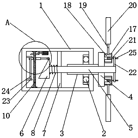
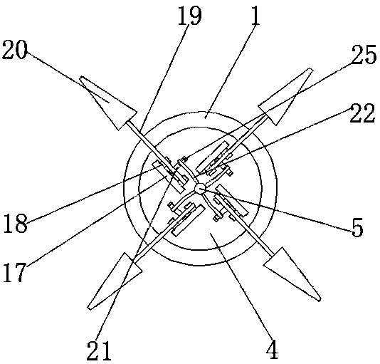
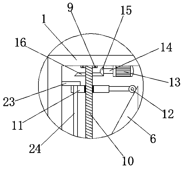
[0018] First implementation: see Figure 1-3 , a pitch control device for a wind power generator, comprising a casing 1, a first rolling bearing 2 is fixedly connected to the midpoint on the right side of the inner wall of the casing 1, a hollow main shaft 3 is movably connected to the inside of the first rolling bearing 2, and the hollow main shaft 3 The right end of the right end runs through the first rolling bearing 2 and the casing 1 from left to right in turn and extends to the outside of the casing 1 and is fixedly connected with the wind wheel disc 4, and the right side of the wind wheel disc 4 and the position corresponding to the hollow main shaft 3 is provided with a push rod 5 , the left end of the push rod 5 runs through the wind wheel disc 4, the hollow main shaft 3 and the casing 1 from right to left, and extends to the inside of the casing 1 to be fixedly connected with a triangular block 6, and the surface of the push rod 5 is located between the triangular blo...

no. 2 approach

[0021]The second embodiment: a pitch control device for a wind power generator, including a casing 1, a first rolling bearing 2 is fixedly connected to the midpoint on the right side of the inner wall of the casing 1, and the inside of the first rolling bearing 2 is flexibly connected There is a hollow main shaft 3, and the right end of the hollow main shaft 3 runs through the first rolling bearing 2 and the casing 1 from left to right and extends to the outside of the casing 1. A wind wheel disk 4 is fixedly connected to the right side of the wind wheel disk 4. And the position corresponding to the hollow main shaft 3 is provided with a push rod 5, and the left end of the push rod 5 runs through the wind wheel disc 4, the hollow main shaft 3 and the casing 1 from right to left in turn, and extends to the inside of the casing 1 and is fixedly connected with a triangular Block 6, the surface of the push rod 5 and the position between the triangular block 6 and the hollow main sh...


PUM


Abstract

The invention discloses a wind driven generator of a wind driven generator. The wind driven generator comprises a machine shell. First rolling bearings are fixedly connected with the middle of the right side of the inner wall of the machine shell. A hollow spindle is movably connected into the first rolling bearings. The right end of the hollow spindle sequentially penetrates through the first rolling beating and the machine shell from left to right, and extends out of the machine shell to be fixedly connected with a wind wheel. A push rod is arranged on the right side of the wind wheel and corresponds to the position of the hollow spindle. Through mutual cooperation of the hollow spindle, the wind wheel, the push rod, a triangular block, a baffle, a reset spring, second rolling bearings,a threaded rod, a threaded sleeve, a pulley, a positive and negative motor, a positive and negative rotating shaft, a first bevel gear, a second bevel gear, fixing plates, bearing seats, rotating blocks and inserting rods, excellent propeller varying effect is achieved, synchronous propeller varying of each blade is achieved. Stability and electric generating efficiency of the wind driven generator are improved, and the service life of the wind driven generator is prolonged.

Description

technical field [0001] The invention relates to the technical field of wind power generators, in particular to a pitch changing device for wind power generators. Background technique [0002] A wind turbine is a device that converts wind energy into electrical energy. It is mainly composed of blades, generators, mechanical parts and electrical components. At present, horizontal axis wind turbines occupy the mainstream position in the market. In order to improve the utilization rate of wind energy and protect wind turbines at the same time, wind turbines often need to be equipped with a pitch device, and a common wind turbine pitch device The effect is not ideal, and it is necessary to set up a pitch changing device for each blade separately, which not only greatly increases the economic cost, but also cannot guarantee that each blade can be pitched synchronously when changing the pitch, which affects the stability of the wind turbine and reduces the wind power generation. T...

Claims


Application Information

Patent Timeline
IPC IPC(8): F03D7/04F03D9/25F03D80/00
CPCF03D7/022F03D7/0236F03D7/0268F03D7/042F03D9/25F03D80/00Y02E10/72
Inventor 石山霞
Owner 国家电投集团广西兴安风电有限公司
Why Eureka
Try Eureka