Pitch change and storage method of a wind turbine

A technology for wind turbines and blades, which is applied in the control of wind turbines, wind turbines, and wind power generation, etc., can solve problems such as unsatisfactory pitch effects, improve safety and operation convenience, improve stability and power generation. Efficiency, reducing bulky effects

Active Publication Date: 2020-05-12
国家电投集团广西兴安风电有限公司
View PDF7 Cites 0 Cited by
  • Summary
  • Abstract
  • Description
  • Claims
  • Application Information

AI Technical Summary

Problems solved by technology

[0003] The purpose of the present invention is to provide a pitch-changing device for a wind-driven generator, which has the advantage of good pitch-changing effect, and solves the common problem that the pitch-changing effect of a pitch-changing device for a wind-driven generator is not ideal

Method used


Image

  • Pitch change and storage method of a wind turbine
  • Pitch change and storage method of a wind turbine
  • Pitch change and storage method of a wind turbine

Examples


no. 1 approach

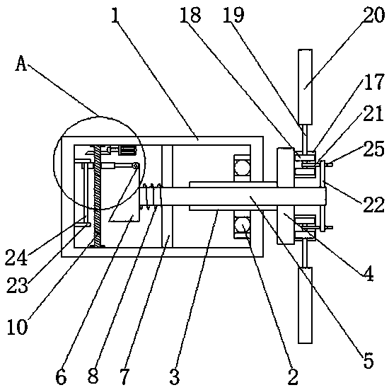
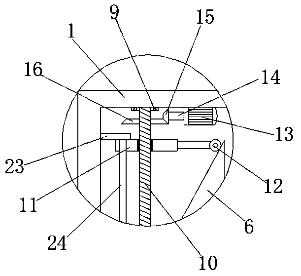
[0018] First implementation: see Figure 1-3 , a pitch control device for a wind power generator, comprising a casing 1, a first rolling bearing 2 is fixedly connected to the midpoint on the right side of the inner wall of the casing 1, a hollow main shaft 3 is movably connected to the inside of the first rolling bearing 2, and the hollow main shaft 3 The right end of the right end runs through the first rolling bearing 2 and the casing 1 from left to right in turn and extends to the outside of the casing 1 and is fixedly connected with the wind wheel disc 4, and the right side of the wind wheel disc 4 and the position corresponding to the hollow main shaft 3 is provided with a push rod 5 , the left end of the push rod 5 runs through the wind wheel disc 4, the hollow main shaft 3 and the casing 1 from right to left, and extends to the inside of the casing 1 to be fixedly connected with a triangular block 6, and the surface of the push rod 5 is located between the triangular blo...

no. 2 approach

[0021]The second embodiment: a pitch control device for a wind power generator, including a casing 1, a first rolling bearing 2 is fixedly connected to the midpoint on the right side of the inner wall of the casing 1, and the inside of the first rolling bearing 2 is flexibly connected There is a hollow main shaft 3, and the right end of the hollow main shaft 3 runs through the first rolling bearing 2 and the casing 1 from left to right and extends to the outside of the casing 1. A wind wheel disk 4 is fixedly connected to the right side of the wind wheel disk 4. And the position corresponding to the hollow main shaft 3 is provided with a push rod 5, and the left end of the push rod 5 runs through the wind wheel disc 4, the hollow main shaft 3 and the casing 1 from right to left in turn, and extends to the inside of the casing 1 and is fixedly connected with a triangular Block 6, the surface of the push rod 5 and the position between the triangular block 6 and the hollow main sh...

no. 3 approach

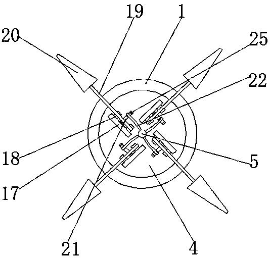
[0026] Embodiment 3: A pitch change and storage method for a wind power generator, wherein the wind power generator includes a casing arranged in sequence in the horizontal direction, a blade support and positioning mechanism, and a plurality of blades, and the blade support and positioning mechanism is rotatably supported on Between the casing and the fan blades, a plurality of fan blades are symmetrically distributed in the center and elastically connected to the fan blade support and positioning mechanism. In the casing, the vertical screw drive structure and the linkage of the triangular blocks set in the horizontal direction The push rod moves back and forth horizontally on the fan blade support positioning mechanism and the symmetrical central axis of multiple fan blades. The front end of the push rod drives the synchronous change of the windward angle of all blades through the rotating block sleeved on the rotation shaft of each blade. , during the horizontal forward and...


PUM


Abstract

The invention relates to a variable pitch and storage method of a wind driven generator. The wind driven generator comprises a machine shell, a supporting and positioning mechanism and blades, whereinblade supporting and positioning mechanism is rotatably supported between the machine shell and the blades, and the blades are symmetrically distributed around the center and elastically and movablyconnected to the blade supporting and positioning mechanism. In the machine shell, a push rod moves horizontally back and forth on the blade supporting and positioning mechanism and the symmetrical central axes of the blades through the linkage of a vertical lead screw transmission structure and a horizontally arranged triangular blocks, the front end of the push rod drives the synchronous same angle change of windward angles of all the blades through rotating blocks, in the horizontal back and forth movement process of the push rod, rotating shafts at the bottoms of the blades are driven by the rotating blocks to perform forward or reverse rotation, the forward or reverse rotation is matched with the current wind speed and the preset rotation speed, so that the stability and the power generation efficiency of the wind driven generator are improved, and the service life of the wind driven generator is prolonged.

Description

technical field [0001] The invention relates to the technical field of wind power generators, in particular to a pitch changing device of a wind power generator and a pitch changing storage method thereof. Background technique [0002] A wind turbine is a device that converts wind energy into electrical energy. It is mainly composed of blades, generators, mechanical parts and electrical components. At present, horizontal axis wind turbines occupy the mainstream position in the market. In order to improve the utilization rate of wind energy and protect wind turbines at the same time, wind turbines often need to be equipped with a pitch device, and a common wind turbine pitch device The effect is not ideal, and it is necessary to set up a pitch changing device for each blade separately, which not only greatly increases the economic cost, but also cannot guarantee that each blade can be pitched synchronously when changing the pitch, which affects the stability of the wind turbi...

Claims


Application Information

Patent Timeline
Patent Type & Authority Patents(China)
IPC IPC(8): F03D7/02
CPCF03D7/0224F03D7/0236Y02E10/72
Inventor 石山霞
Owner 国家电投集团广西兴安风电有限公司
Why Eureka
Try Eureka