
Magnetic fluid reciprocating sealing structure

A sealing structure and magnetic fluid technology, which is applied in the direction of engine sealing, engine components, mechanical equipment, etc., can solve the problems of increasing magnetic field strength, magnetic flux leakage, etc., and achieve the effect of good sealing and pressure resistance performance

Active Publication Date: 2018-12-18
GUANGXI UNIVERSITY OF TECHNOLOGY
View PDF2 Cites 0 Cited by
  • Summary
  • Abstract
  • Description
  • Claims
  • Application Information

AI Technical Summary

Problems solved by technology

According to the inventor, the lower permanent magnet ring of this patent adopts a parallel structure, the main purpose is to increase the magnetic field strength, and there is still serious magnetic flux leakage between the upper permanent magnet ring and the pole piece

Method used


Image

  • Magnetic fluid reciprocating sealing structure
  • Magnetic fluid reciprocating sealing structure
  • Magnetic fluid reciprocating sealing structure

Examples


Embodiment Construction

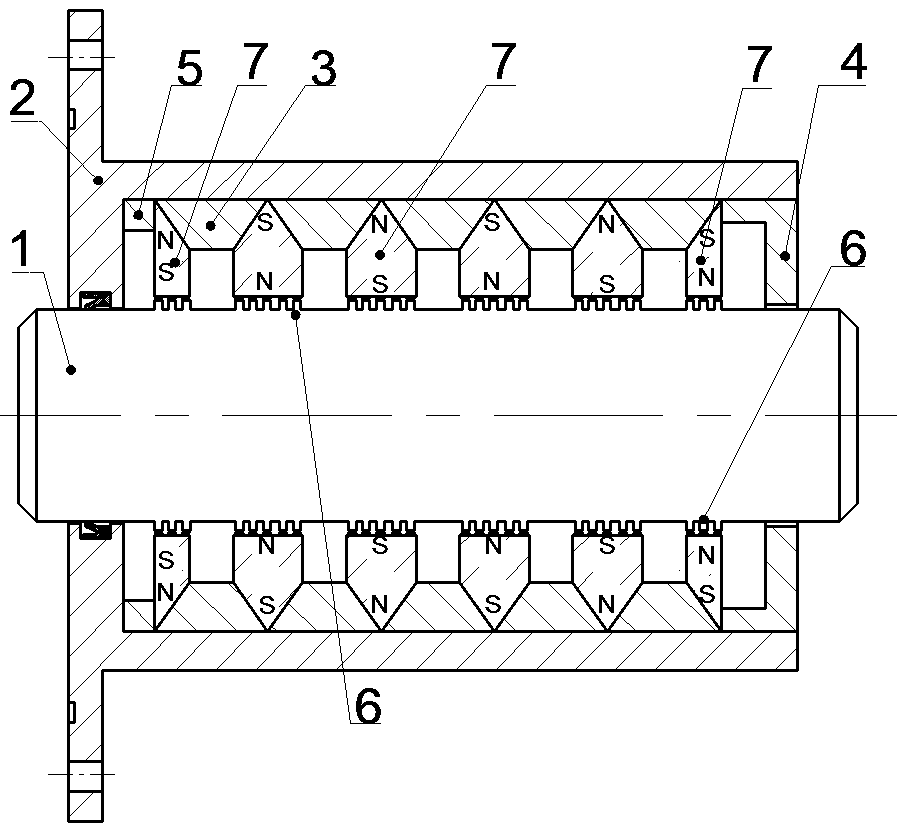
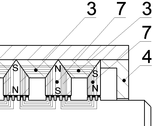
[0026] Such as Figure 2-3 As shown, a ferrofluid reciprocating sealing structure includes a hollow shell 2, one end of which is closed and the other end is open. A through hole is opened in the center of the closed end face of the housing 2 .

[0027] It also includes a shaft 1 penetrating from the through hole to the inner cavity of the housing 2 . In the space between the outer surface of the shaft 1 and the inner wall of the casing 2, a plurality of radially magnetized permanent magnet rings 7 are arranged axially at intervals. An annular pole piece 3 is interposed between two adjacent radially magnetized permanent magnet rings 7 . The cross section of the pole piece 3 is a trapezoid with a wide top and a narrow bottom. Various forms of trapezoid are applicable, but from the perspective of increasing the contact area as much as possible, the cross section of the pole shoe 3 is an isosceles trapezoid.

[0028] Each radially magnetized permanent magnet ring 7 is provided...


PUM


Abstract

The invention discloses a magnetic fluid reciprocating sealing structure. A plurality of radial magnetizing-type permanent magnet rings are arranged at intervals in the axial direction in the space between the outer surface of a shaft and the inner wall of a shell, annular pole shoes are sandwiched between every two adjacent radial magnetizing-type permanent magnet rings, and the cross sections ofthe pole shoes are trapezoids with wide upper parts and narrow lower parts; the radial magnetizing-type permanent magnet rings are provided with bonding surfaces which can be correspondingly bonded to the side surfaces of the pole shoes, and the two side surfaces of the pole shoes are separately connected and matched with every two adjacent radial magnetizing-type permanent magnet rings in an abutting mode; the outer circles of the radial magnetizing-type permanent magnet rings and the outer circles of the pole shoes are connected to the inner wall of the shell in an abutting mode; gaps existbetween the inner circular surfaces of the radial magnetizing-type permanent magnet rings and the outer surface of the shaft, and magnetic fluid is injected at the gaps; and the polarities of the magnetic poles of every two adjacent radial magnetizing-type permanent magnet rings are opposite. The trapezoidal cross-section design increases the contact area between the pole shoes and the radial magnetizing-type permanent magnet rings, and the radial magnetizing-type permanent magnet rings on both sides wrap the pole shoes, so that magnetic leakage hardly occurs, and the sealing and pressure resistance performances are better.

Description

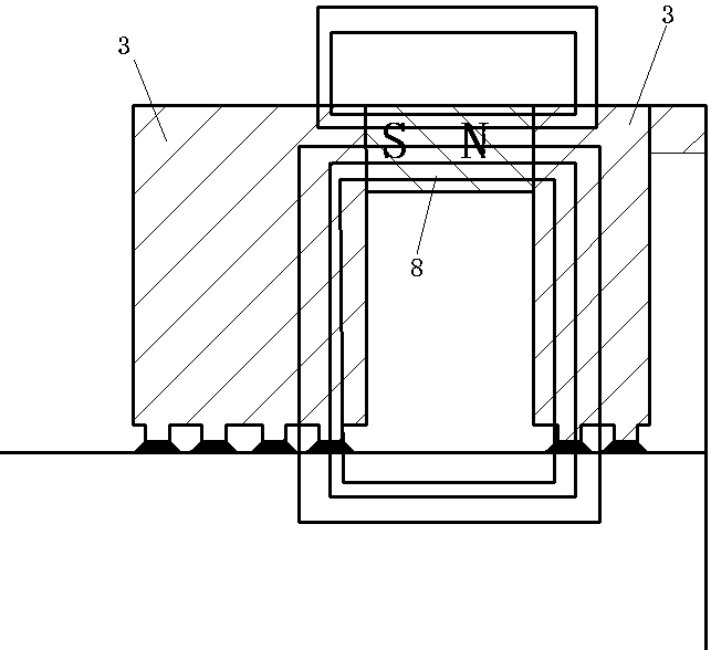
technical field [0001] The invention belongs to the field of mechanical engineering seals, in particular to a magnetic fluid reciprocating seal structure. Background technique [0002] The existing magnetic fluid sealing structure generally includes a housing with a hollow cavity, a shaft, a permanent magnet and a pole shoe are arranged between the shaft and the housing for magnetic fluid sealing, and the inner ring of the pole shoe is provided with pole teeth. [0003] The leakage of the magnetic field in the magnetic fluid seal leads to the reduction of the magnetic field strength in the magnetic circuit, thereby reducing the pressure resistance of the magnetic fluid seal. Such as figure 1 As shown, at present, the pole piece 3 and the axially magnetized permanent magnet ring 8 are both standard annular structures, the cross-sections of both are rectangular, and the joint surface of the two is the main location where the magnetic flux leakage occurs in the magnetic fluid ...

Claims


Application Information

Patent Timeline
IPC IPC(8): F16J15/40
CPCF16J15/43
Inventor 杨小龙陈帆余冬燕
Owner GUANGXI UNIVERSITY OF TECHNOLOGY
Learn More