Operable observation recording device for cryoelectron microscope

A cryo-electron microscope and recording device technology, which is used in measurement devices, material analysis using wave/particle radiation, instruments, etc. Shooting quality, guarantee observation, guarantee comprehensive effect

Active Publication Date: 2018-12-18
义乌市研创工业设计有限公司
View PDF15 Cites 7 Cited by
  • Summary
  • Abstract
  • Description
  • Claims
  • Application Information

AI Technical Summary

Problems solved by technology

However, the freedom of operation of this device is not high, and it cannot guarantee a comprehensive shooting angle. At the same time, the liquefied nitrogen will also affect the shooting angle.

Method used


Image

  • Operable observation recording device for cryoelectron microscope
  • Operable observation recording device for cryoelectron microscope
  • Operable observation recording device for cryoelectron microscope

Examples


specific Embodiment approach 1

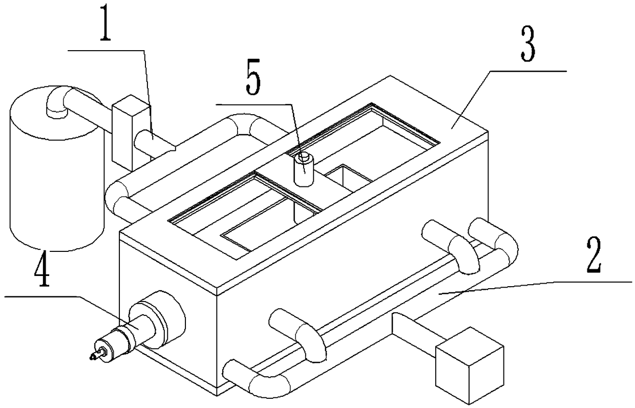
[0029] Such as Figure 1 to Figure 13As shown, an operable observation and recording device for a cryo-electron microscope includes a liquid nitrogen supply device 1, a vacuum device 2, an experimental carrier 3, a manual operation device 4 and a low-temperature shooting and recording device 5, and the liquid nitrogen supply device 1 is fixed Connected to the front end of the experimental carrier 3, the vacuum device 2 is fixedly connected to the rear end of the experimental carrier 3, the liquid nitrogen supply device 1 and the vacuum device 2 are connected to the experimental carrier 3, and the manual operation device 4 is fixedly connected to the left end of the experimental carrier 3. The photographing and recording device 5 is clearance-fitted on the upper end of the experiment carrier 3 , and the manual operation device 4 and the low-temperature photographing and recording device 5 are both arranged in the experiment carrier 3 . The selection of low-temperature shooting ...

specific Embodiment approach 2

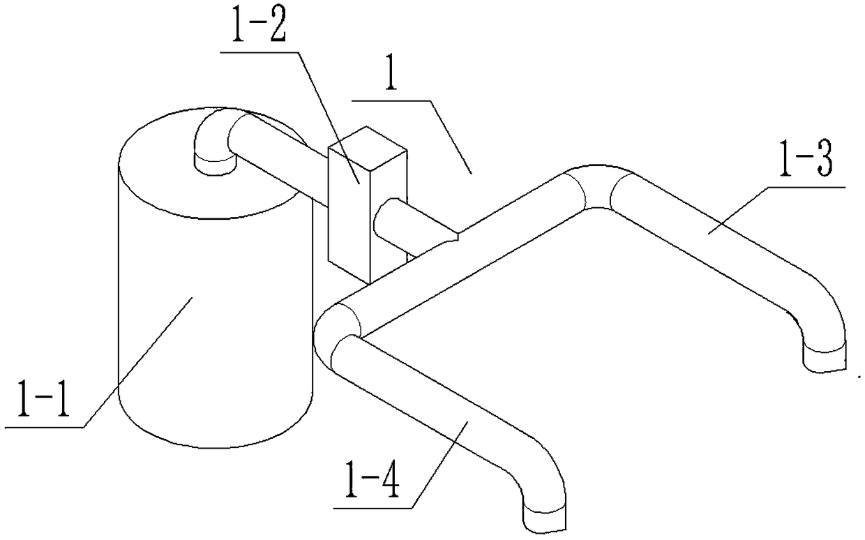
[0030] Such as Figure 1 to Figure 13 As shown, this embodiment will further describe Embodiment 1. The liquid nitrogen supply device 1 includes a Dewar bottle 1-1, a liquid nitrogen pump 1-2, a right liquid nitrogen pipeline 1-3 and a left liquid nitrogen pipeline 1- 4. The liquid nitrogen pump 1-2 is connected to the inside of the Dewar bottle 1-1 through the bellows, the liquid nitrogen pump 1-2 is connected to the right liquid nitrogen pipeline 1-3 and the left liquid nitrogen pipeline 1-4, and the right liquid nitrogen pipeline 1- 3 and the left liquid nitrogen pipeline 1-4 are fixedly connected to the experimental carrier 3.

specific Embodiment approach 3

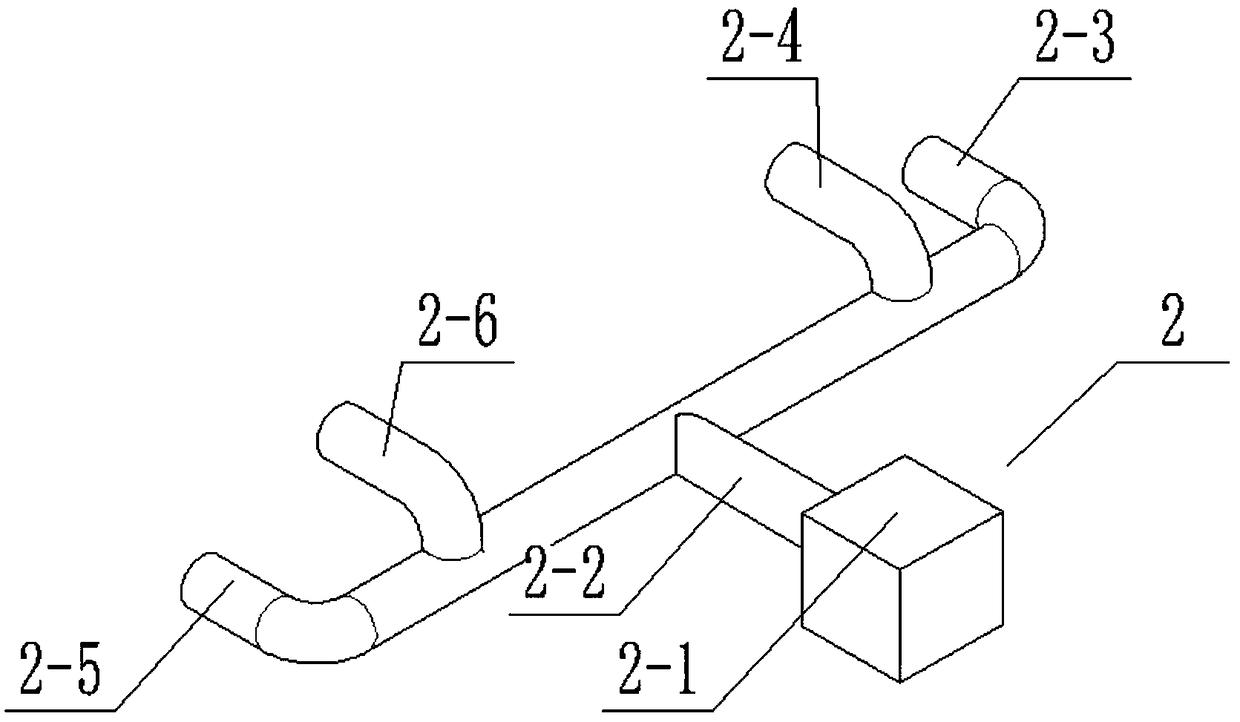
[0031] Such as Figure 1 to Figure 13 As shown, this embodiment will further illustrate the second embodiment. The vacuum device 2 includes a vacuum pump 2-1, a main vacuum pipeline 2-2, a right vacuum pipeline 2-3, a right second vacuum pipeline 2-4, a left Two vacuum pipelines 2-5 and the left one vacuum pipeline 2-6, the right one vacuum pipeline 2-3, the right two vacuum pipelines 2-4, the left two vacuum pipelines 2-5 and the left one vacuum pipeline 2-6 are all connected with the vacuum main The pipeline 2-2, the back end of the vacuum main pipeline 2-2 communicates with the vacuum pump 2-1. The pipes are all connected by welding.


PUM


Abstract

The invention relates to the field of biological electron microscopes, in particular to an operable observation recording device for a cryoelectron microscope. The operable observation recording device comprises a liquid nitrogen supply device, a vacuum device, an experiment carrier, a manual operation device and a low-temperature shooting recording device; the liquid nitrogen supply device is fixedly connected to the front end of the experiment carrier; the vacuum device is fixedly connected to the rear end of the experiment carrier; the liquid nitrogen supply device and the vacuum device areboth communicated with the experiment carrier; the manual operation device is fixedly connected to the left end of the experiment carrier; the low-temperature shooting recording equipment is arrangedat the upper end of the experiment carrier in a clearance fit manner; and the manual operation device and the low-temperature shooting recording device are both arranged in the experiment carrier. The operable observation recording device has the beneficial effects that a relatively vacuum environment is provided for a frozen biological sample, so that a freezing environment is guaranteed; through vacuum isolation, the experiment safety is guaranteed; and a shooting angle of the sample can be adjusted in a multi-angle mode in all aspects, so that the shooting quality is guaranteed, the comprehensive observation is guaranteed, and the influence of liquid nitrogen on shooting in a vaporization process is reduced.

Description

technical field [0001] The invention relates to the field of biological electron microscopy, in particular to an operable observation and recording device for cryo-electron microscopy. Background technique [0002] The use of electron microscopy has broadened the horizons of bioengineering and made great contributions to bioengineering. Patent No. CN201610617959.9 discloses a vacuum moving device for scanning / transmission electron microscope correlation analysis, including a vacuum cavity connected to the scanning electron microscope, a two-dimensional translation stage inside it, and an eccentric sleeve of the transmission electron microscope sample rod; The front end of the vacuum chamber is connected to the flange of the scanning electron microscope chamber; the vacuum chamber is equipped with a two-dimensional translation stage external knob; the interior of the chamber is installed with a two-dimensional translation stage for the precise selection of the SEM electron be...

Claims


Application Information

Patent Timeline
Patent Type & Authority Applications(China)
IPC IPC(8): G01N23/00
CPCG01N23/00
Inventor 王阳
Owner 义乌市研创工业设计有限公司
Why Eureka
Try Eureka