Visualized experimental device for CHF research in bidirectionally visible rectangular narrow channel

An experimental device and narrow channel technology, applied in the direction of measuring devices, instruments, scientific instruments, etc., can solve the problems of different gaps in rectangular flow channels, the inability to observe the growth of bubbles from the side, and the inability to ensure the same degree of screwing of bolts, etc., to achieve changing flow The effect of reducing the road gap, avoiding expansion and deformation, and reducing the thickness of the narrow surface

Active Publication Date: 2018-12-18
HARBIN ENG UNIV
View PDF5 Cites 8 Cited by
  • Summary
  • Abstract
  • Description
  • Claims
  • Application Information

AI Technical Summary

Problems solved by technology

During the installation process, it is impossible to ensure that all the bolts are screwed to the same degree, which results in different clearances at different sections of the rectangular flow channel.
Secondly, the traditional rectangular channel experimental device can only photograph the aggregation behavior of the bubbles from the front, and cannot observe the growth of the bubbles and some important parameters that affect the critical heat flux from the side, such as the thickness of the bubble layer and the thickness of the liquid film.
Finally, the channel gap of the above-mentioned experimental device is fixed, so it is impossible to study the influence of the gap effect on the flow

Method used


Image

  • Visualized experimental device for CHF research in bidirectionally visible rectangular narrow channel
  • Visualized experimental device for CHF research in bidirectionally visible rectangular narrow channel
  • Visualized experimental device for CHF research in bidirectionally visible rectangular narrow channel

Examples


Embodiment Construction

[0021] The present invention will be further described in detail below in conjunction with the accompanying drawings and specific embodiments.

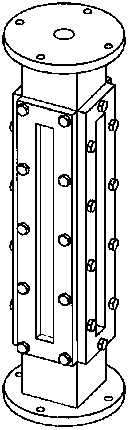
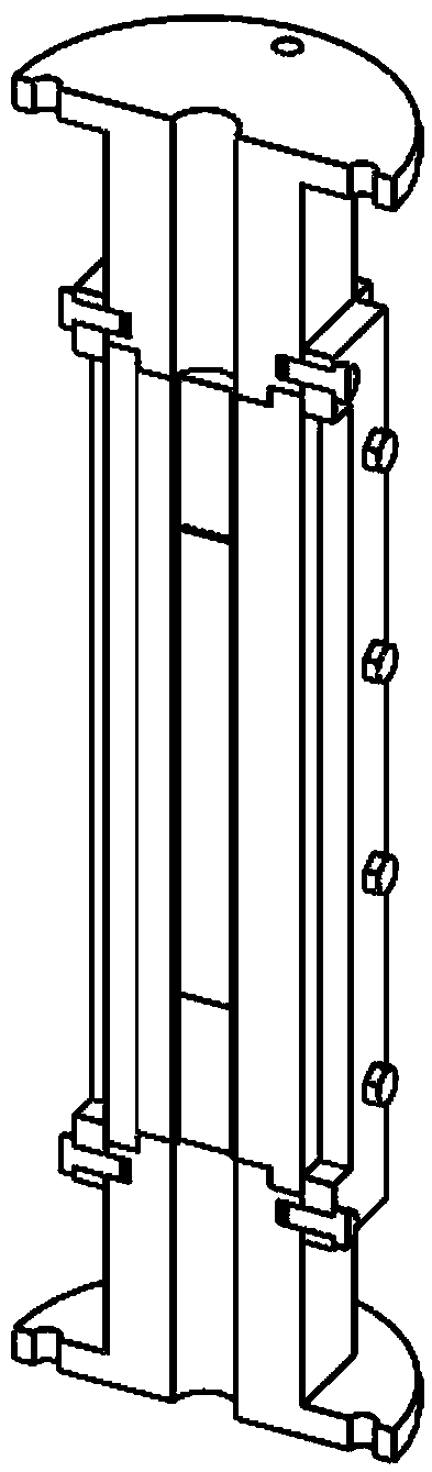
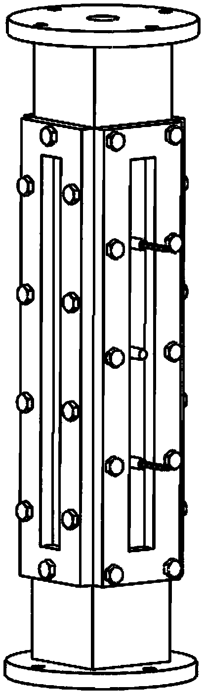
[0022] The main purpose of the present invention is to provide a two-way visual CHF research visualization experiment device in a narrow rectangular channel. The device mainly includes a heating plate, a substrate, a wide side quartz glass, a narrow side quartz glass, a shell, a pressure bearing plate, a gasket for sealing and a bolt for connection. The fluid flows into the narrow rectangular channel from the lower flange hole, and is heated and boiled by the heating plate to form a two-phase mixture and flows out from the upper flange hole. Compared with the traditional rectangular channel visualization device, the visualization device adopted in the present invention can not only observe the evolution of the flow pattern and the behavior of the bubbles from the front, but also observe the generation, growth, aggregation and detachme...


PUM

PropertyMeasurementUnit
Thicknessaaaaaaaaaa

Abstract

The invention particularly relates to a visualized experimental device for CHF research in a bidirectionally visible rectangular narrow channel, belonging to the field of flow boiling visualization research. The experimental device comprises fastening bolts, a graphite gasket, flanges, a heating plate, a wide-side quartz glass, a wide-sided bearing plate, a fluoro rubber gasket, a narrow-sided quartz glass, a narrow-sided bearing plate, a housing, a substrate, and a support column. The experimental device used in the invention is all quartz glass on three sides, therefore, the behaviors of generation, aggregation, growth and detachment of bubbles on the heating surface can be observed from the side, and parameters such as a bubble layer and liquid film thickness can be measured; the heating plate is slightly narrower than the base, therefore, the rectangular flow channel corner effect is avoided; the heating plate is shorter in axial direction than the substrate, therefore, the inlet and outlet effect is eliminated; the substrate is made of insulating ceramic material, so that the heating plate is completely insulated from other parts of the experimental section; three support columns are welded on the heating plate and fixed to the substrate, so as to avoid expansion deformation of the heating plate at high temperature; and the flow path gap can be changed by changing the thickness of the gasket between the wide-side quartz glass and the housing.

Description

technical field [0001] The invention belongs to the field of flow boiling visualization research, in particular to a two-way visual CHF research visualization experiment device in a rectangular narrow channel. Background technique [0002] The critical heat flux CHF is the heat transfer limit of flow boiling. Accurately predicting the critical heat flux value is of great significance for reactor design and operation under accident conditions. Plate-type fuel assemblies with rectangular narrow channel features are widely used in research and experimental reactors and integrated reactors because of their compact structure, low fuel pellet temperature, and large heat transfer area. Some of the existing empirical relations for predicting the critical heat flux in narrow rectangular channels are all fitted based on their own experimental data. The accuracy depends strongly on the similarity of the experimental conditions and cannot be extended to other conditions. Therefore, the...

Claims


Application Information

Patent Timeline
IPC IPC(8): G01N25/00
CPCG01N25/00
Inventor 曹夏昕何海沙于德海胡俭李娜王金成程俊王钦
Owner HARBIN ENG UNIV
Why Eureka
Try Eureka