An electric core pole piece group fixing frame and a battery with the battery pole piece group fixing frame

A pole piece group and fixing frame technology, which is applied in battery pack components, secondary battery manufacturing, circuits, etc., can solve the problems of reducing the performance of power batteries in groups, affecting the consistency of battery production, and dislocation of battery pole pieces. , to achieve efficient assembly process and production consistency, excellent battery performance, and eliminate swelling

Active Publication Date: 2019-03-15
BEIJING PRIDE NEW ENERGY BATTERY
View PDF3 Cites 2 Cited by
  • Summary
  • Abstract
  • Description
  • Claims
  • Application Information

AI Technical Summary

Problems solved by technology

Due to the large number of layers of the battery pole piece group, the battery pole piece group is removed from the stacker, the battery pole piece group enters the battery case, and the battery tab is riveted, welded or bolted to the terminal. During the assembly operation of series battery manufacturing, the movement and assembly of the cell electrode group can easily lead to misalignment between the cell electrodes
Even when stacking sheets on a fully automatic stacking machine, there is still the problem of aligning each group of cell pole pieces within the allowable error range
In addition, during the charging and discharging process of the battery, the thickness of the internal cell pole piece group will increase by more than a few millimeters due to the expansion of the lattice, causing the battery case to be squeezed and deformed.
This will seriously affect the production consistency of the battery and reduce the performance of the battery pack

Method used


Image

  • An electric core pole piece group fixing frame and a battery with the battery pole piece group fixing frame
  • An electric core pole piece group fixing frame and a battery with the battery pole piece group fixing frame
  • An electric core pole piece group fixing frame and a battery with the battery pole piece group fixing frame

Examples


Embodiment 1

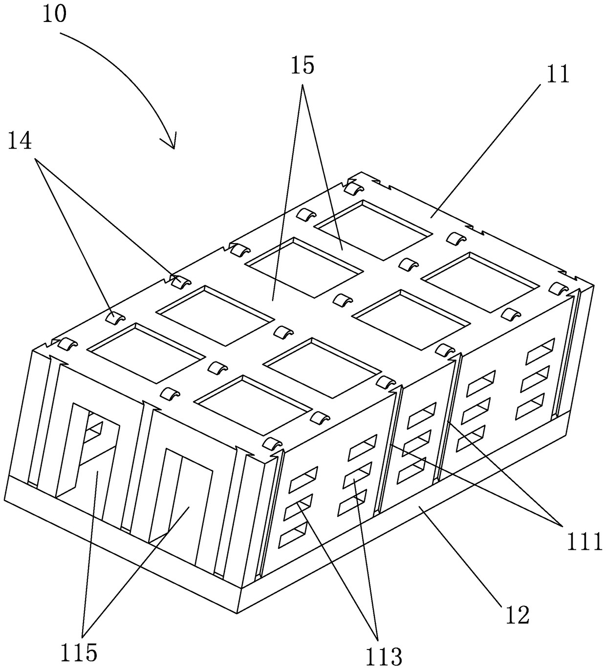
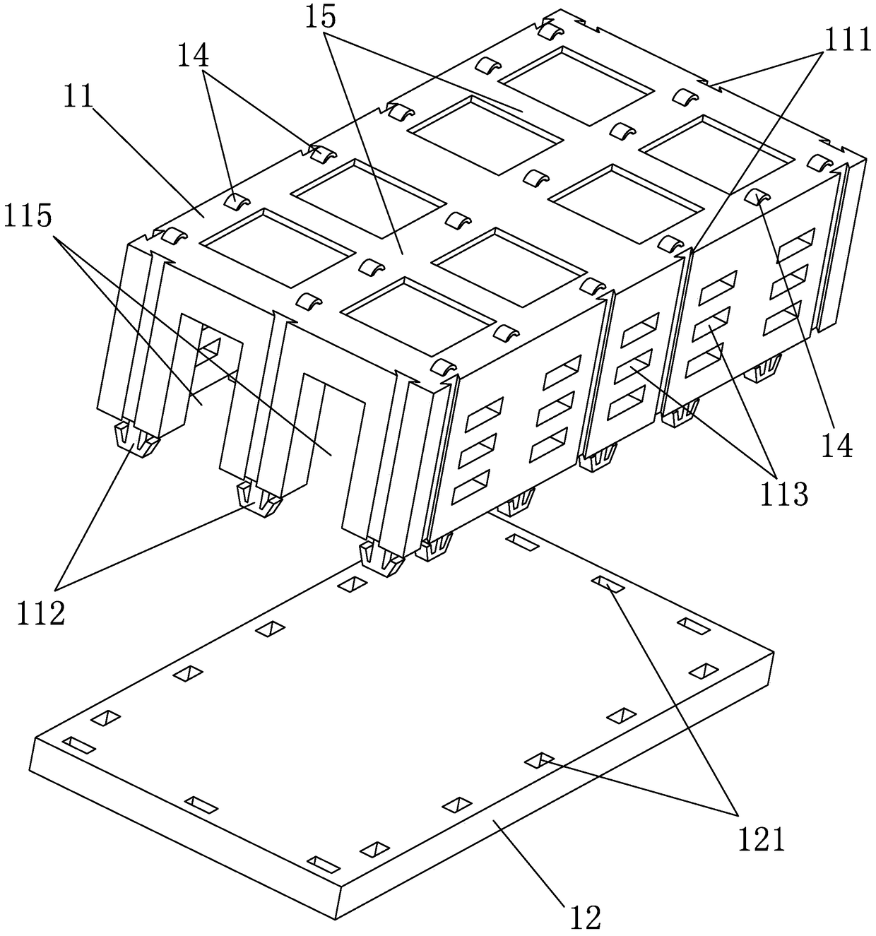
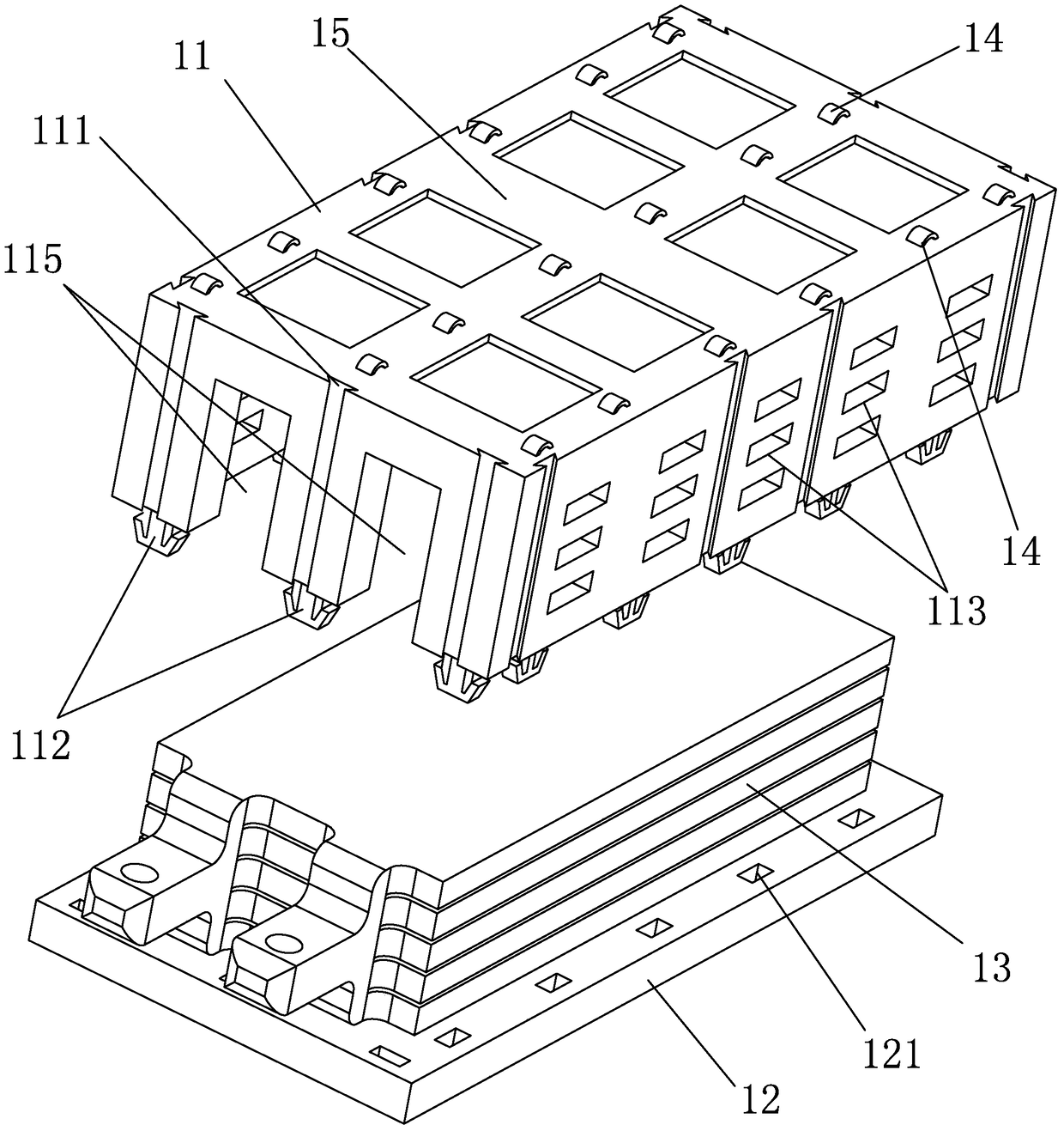
[0039] Figure 1 to Figure 7 An embodiment of a battery pole piece group fixing frame is given.

[0040] Such as Figure 1 to Figure 7 As shown, the battery pole piece group fixing frame 10 of this example includes an upper cover 11 and a bottom plate 12 , elastic sheets 14 and reinforcing ribs 15 are provided on the upper surface of the upper cover 11 and the lower surface of the bottom plate 12 . The upper cover 11 is provided with a grasping insertion hole 111 and a through hole 113 .

[0041] In this example, the grasping jack 111 is a dovetail groove structure, such as figure 2 , image 3 and Figure 7 shown.

[0042] In this example, the lug outlet 115 of the upper cover 11 is arranged on the same side, as image 3 shown.

[0043]In this example, the connection mode between the upper cover 11 and the bottom plate 12 is a snap connection, and the upper cover 11 is provided with a hasp hook 112 matching with the hasp lock hole 121 of the bottom plate 12 . The edge...

Embodiment 2

[0049] Figure 8 ~ Figure 13 Provides another embodiment of the cell pole piece group fixing frame.

[0050] The difference between this example and Example 1 is:

[0051] In this example, the lug outlet 115 of the upper cover 11 is arranged on the opposite side, as Figure 8 and Figure 11 shown.

[0052] In this example, the upper cover 11 and the bottom plate 12 are connected by an external clamping device. The upper cover 11 is provided with an upper cover clamping step 114 that facilitates the clamping connection of the external clamping device 16. The bottom plate clamping step 123 of device 16 clamping connection, as Figure 10 , Figure 11 and Figure 12 shown.

[0053] In this example, the through hole 113 of the loam cake 11 is circular, as Figure 8 and Figure 12 shown.

[0054] In this example, the lower surface of the base plate 12 is provided with a base plate concave hole 122, such as Figure 9 , Figure 13 shown.

[0055] In this example, the shap...

Embodiment 3

[0059] Figure 14 An embodiment of a battery with the battery pole piece group fixing frame is given.

[0060] The battery of this example includes a cell pole piece set 13 and a battery casing 20 , and the battery of this example also has a battery pole piece set fixing frame as described in Embodiment 1.

[0061] In this example, the thickness of the cell pole piece group 13 is 80 mm.

[0062] The technical scheme of the present invention can not only keep the cell pole piece group inside the battery in a compressed state, but also prevent the battery pole pieces from being dislocated and the distance between them increased during the production and assembly process of the battery pole piece group, and reduce the internal resistance of the battery , and can eliminate the expansion of the cell pole piece group caused by the expansion and contraction of the electrode material lattice inside the battery, and prevent the expansion and deformation of the battery case, so that th...


PUM

PropertyMeasurementUnit
thicknessaaaaaaaaaa
thicknessaaaaaaaaaa

Abstract

The invention discloses a battery pole piece group fixing frame, which is characterized in that the battery pole piece group fixing frame includes a bottom plate and an upper cover, the lower surface of the bottom plate and the upper surface of the upper cover are provided with elastic sheets and reinforcing ribs, and the upper cover also There are grasping jacks and through holes, and the bottom surface of the bottom plate is also provided with bottom plate concave holes. The connection mode of the bottom plate and the upper cover is a buckle connection or an external clamping device connection. The material of the bottom plate and the upper cover is aluminum, nickel, poly Propylene, polyethylene and other materials. The invention also discloses a battery provided with the fixing frame of the cell pole piece group. The invention can prevent the dislocation and spacing increase of the battery pole pieces during the production and assembly process of the battery pole piece group, prevent the expansion and deformation of the battery case, and ensure that the battery has excellent electrochemical performance. In addition, the present invention can also ensure that different types of batteries have efficient assembly process and production consistency, improve the assembly accuracy and production efficiency of batteries, and reduce the manufacturing cost.

Description

technical field [0001] The invention relates to the technical field of batteries, in particular to a cell pole piece group fixing frame and a battery with the battery cell pole piece group fixing frame. Background technique [0002] For the large-capacity rectangular lithium-ion power battery pole piece group manufactured by the stacking process, the number of pole pieces is relatively large. If one positive electrode, one negative electrode, and two separators are used as one layer, more than 100 layers can meet the capacity standard. Due to the large number of layers of the battery pole piece group, the battery pole piece group is removed from the stacker, the battery pole piece group enters the battery case, and the battery tab is riveted, welded or bolted to the terminal. During the assembly operation of series battery manufacturing, the movement and assembly action of the cell pole piece group can easily lead to misalignment between the battery pole pieces. Even when s...

Claims


Application Information

Patent Timeline
Patent Type & Authority Patents(China)
IPC IPC(8): H01M2/10H01M10/04H01M50/20H01M50/204H01M50/244
CPCY02E60/10Y02P70/50
Inventor 顾辉田边李春小胡大海
Owner BEIJING PRIDE NEW ENERGY BATTERY
Why Eureka
Try Eureka