Preparation device and method of surface gradient scattering cladding optical power stripper

A technology for preparing devices and strippers, which is applied in the direction of instruments, light guides, optics, etc., and can solve the problems of reduced filtering power, cladding light leakage, and severe temperature rise on the device surface

Active Publication Date: 2019-08-09
INST OF SEMICONDUCTORS - CHINESE ACAD OF SCI
View PDF5 Cites 0 Cited by
  • Summary
  • Abstract
  • Description
  • Claims
  • Application Information

AI Technical Summary

Problems solved by technology

The uniform corrosion structure design is often used in the peeling area, and its defect is that it cannot take into account the temperature rise uniformity and power attenuation performance of the device
When the corrosion time is too long and the density of scattering crystal particles on the surface of the optical fiber is high, although high power attenuation performance can be achieved, the cladding light will leak a large amount in a very short distance, which is prone to local thermal effects and the temperature rise of the device surface severe
When the corrosion time is too short and the density of scattering crystal particles on the surface of the fiber is small, the cladding light is slowly filtered out along the axial direction of the stripping zone. Although the temperature rise of the device is reduced, the filtered power is greatly reduced at the same length

Method used


Image

  • Preparation device and method of surface gradient scattering cladding optical power stripper
  • Preparation device and method of surface gradient scattering cladding optical power stripper
  • Preparation device and method of surface gradient scattering cladding optical power stripper

Examples


preparation example Construction

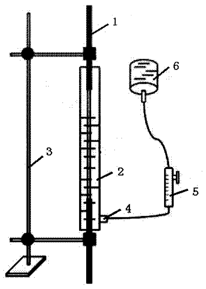
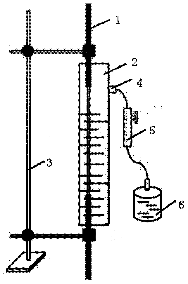
[0035] In the first exemplary embodiment of the present disclosure, a method for preparing a surface gradient scattering cladding optical power stripper is also provided. Figure 6 It is a flow chart of a method for preparing a surface gradient scattering cladding optical power stripper according to an embodiment of the present disclosure. Such as Figure 6 As shown, it includes: step A: peel off the coating layer of the middle section of the optical fiber to be corroded, and expose the bare fiber section; The cylinder is parallel and does not touch the reaction cylinder; step C: the container containing the corrosive solution is connected to the injection hole through the pipeline, and the corrosive solution is injected into the reaction cylinder; step D: the flow rate of the corrosive solution injected into the reaction cylinder is controlled by a flow meter, Control the rising speed of the corrosive liquid in the reaction cylinder, along the laser transmission direction, s...


PUM


Abstract

The disclosure provides a surface gradient scattering type clad optical power stripper manufacturing device and method. The manufacturing device comprises a reaction tube, a holder, an injection holeand a flow meter; the bottom of the reaction tube is provided with a connecting hole, and a fiber to be corroded passes through the connecting hole and is hermetically connected with the bottom of thereaction tube; the fiber to be corroded is connected to the holder; the injection hole is formed in the reaction tube; a container containing a corrosive liquid is connected to the injection hole through a pipeline, the corrosive liquid is injected into the reaction tube, and the flow meter is further arranged on the pipeline. According to the gradient corrosion device, the corrosion time for a clad surface continuously increases in the axial direction of the fiber to be corroded and in the laser transmission direction, and the density of crystal particles corresponding to the clad surface gradually increases, thereby achieving the effect of gradually increasing the clad light scattering rate.

Description

technical field [0001] The present disclosure relates to the field of fiber laser technology, in particular to a preparation device and method for a surface gradient scattering cladding optical power stripper. Background technique [0002] Cladding pumping technology achieves kilowatt-level fiber laser output. But the residual pump light at the end of the output stage of the laser amplifier degrades the output beam quality of the fiber laser. What's more serious is that when the residual pump light is transmitted between adjacent power stages, it will generate additional heat load on the passive devices between adjacent power stages in the laser system, which will endanger the stable operation of passive devices. In addition, high-power fiber lasers are widely used in the field of laser processing. When the fiber laser acts on the surface of the material to be processed, a large amount of scattered light on the surface of the material will be coupled into the inner claddin...

Claims


Application Information

Patent Timeline
Patent Type & Authority Patents(China)
IPC IPC(8): G02B6/245H01S3/067
Inventor 林学春邹淑珍陈寒孙静于海娟张志研王奕博
Owner INST OF SEMICONDUCTORS - CHINESE ACAD OF SCI
Why Eureka
Try Eureka