Electrical connector

A technology of electrical connectors and contact parts, applied in contact parts, modification by conduction heat transfer, cooling/ventilation/heating transformation, etc., can solve the problems of high contact point temperature and power terminal heating, etc. The effect of reducing heat generation and improving transmission reliability

Inactive Publication Date: 2018-12-18
ALLTOP ELECTRONICS SU ZHOU +1
View PDF0 Cites 8 Cited by
  • Summary
  • Abstract
  • Description
  • Claims
  • Application Information

AI Technical Summary

Problems solved by technology

[0002] The power terminal of a traditional electrical connector is usually formed from one or divided into multiple contact arms from the front end of the metal sheet. When the electrical connector transmits current, the highest temperature of the power terminal is the contact point area of ​​the contact arm. The contact method of the contact point is only line contact, which limits the current channel. In the case of the limited width of the power terminal, the power terminal is very easy to generate heat due to the current impedance, which will lead to excessive temperature of the contact point.

Method used


Image

  • Electrical connector
  • Electrical connector
  • Electrical connector

Examples


Embodiment Construction

[0029] The present invention will be described in detail below with reference to the embodiments shown in the accompanying drawings. However, this embodiment does not limit the present invention, and structural, method, or functional changes made by those skilled in the art according to this embodiment are all included in the protection scope of the present invention.

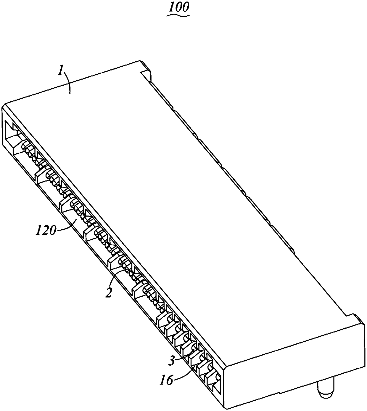
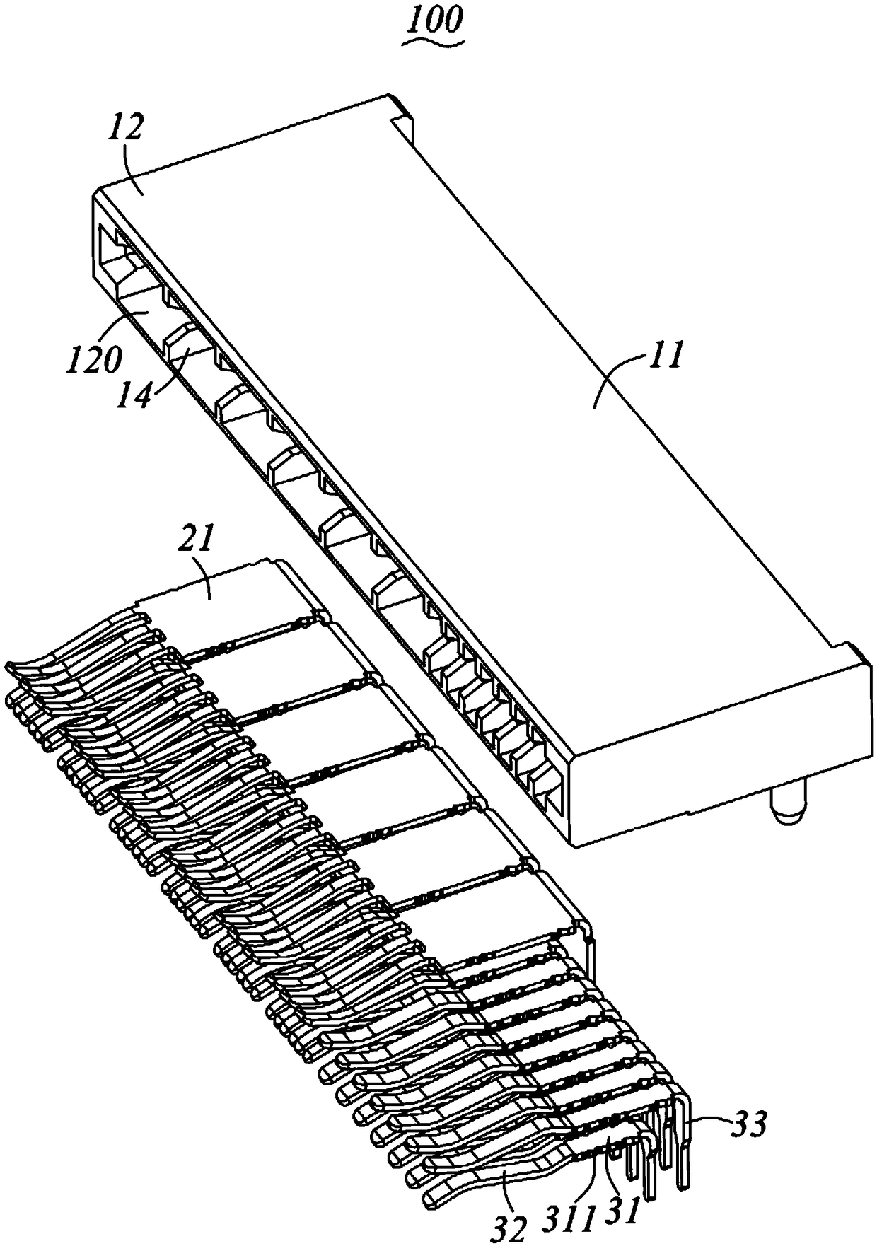
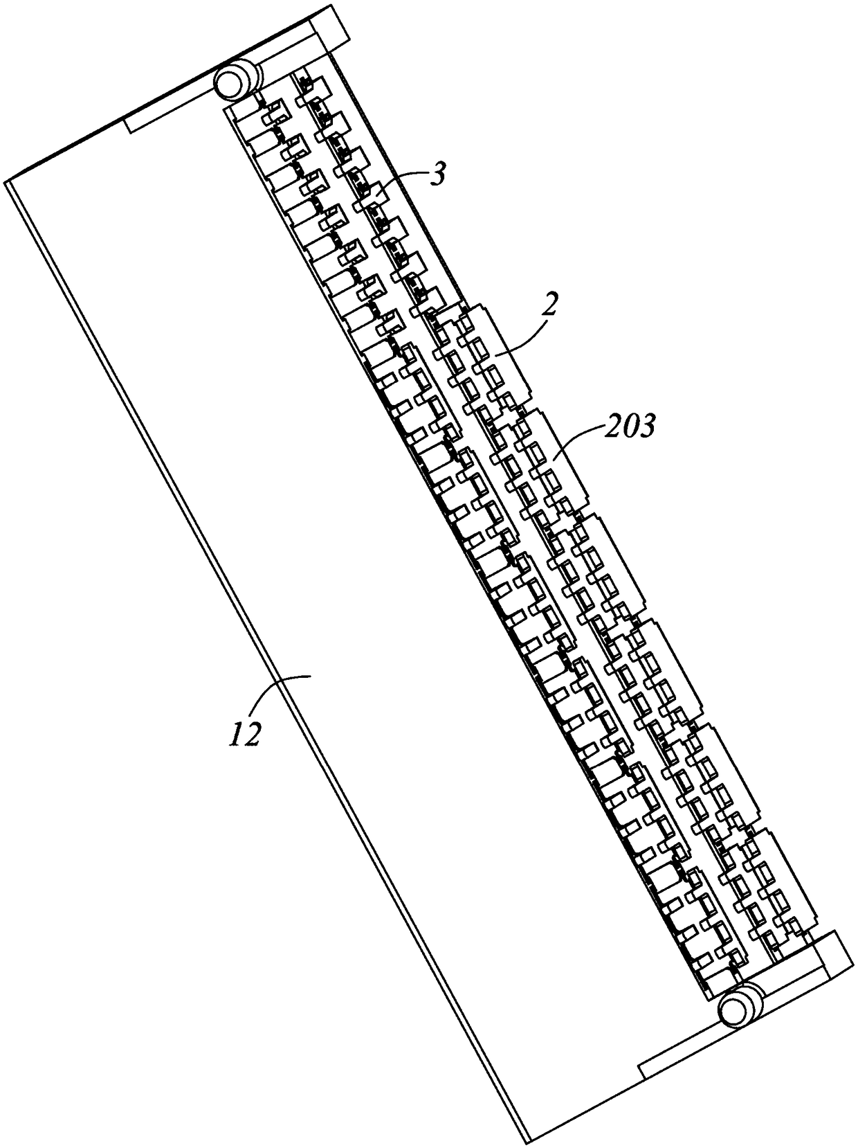
[0030] Please refer to Figure 1 to Figure 9 Shown is a first preferred embodiment of the electrical connector of the present invention. The electrical connector 100 includes an insulating body 1 and a plurality of power terminal pairs 2 fixed on the insulating body 1 . For the convenience of description, the following description will take the mating end of the electrical connector 100 as the front end and the opposite end of the electrical connector 100 as the rear end, that is, the front-to-rear direction is the connection between the electrical connector 100 and the mating element (not shown). The docking ...


PUM


Abstract

An electrical connector which is provided with an insulating body and a plurality of power terminal pairs fixed to the insulating body, the insulating body has a base portion, a butt portion extendingforwardly from the base portion and a plurality of first terminal grooves extending in the front-rear direction, the power supply terminal pair is accommodated in a corresponding first terminal groove, and each of the power supply terminal pairs comprises two power supply terminals, each of the power supply terminals is provided with a retaining portion retained in the first terminal groove, A plurality of contact portions extending forward from one end of the retaining portion and a welding portion extending from the other end of the retaining portion are arranged in a row in the height direction of the contact portions of two power supply terminals in each pair of power supply terminals, and the plurality of contact portions of the two power supply terminals are alternately arranged inthe lateral direction and circularly. The electric connector of the invention can effectively improve the heating condition of a pair of power supply terminals.

Description

technical field [0001] The present invention relates to an electrical connector, in particular to an electrical connector capable of effectively improving the heating condition of conductive terminals. Background technique [0002] The power terminal of the traditional electrical connector is usually formed from the front end of the metal sheet or divided into multiple contact arms. When the electrical connector transmits current, the highest temperature position of the power terminal is the contact point area of ​​the contact arm. The contact mode of the contact point is only line contact, which restricts the current path. In the case of limited width of the power terminal, the power terminal is easily heated due to the current impedance, which in turn causes the contact point temperature to be too high. [0003] In view of this, it is necessary to improve the existing electrical connectors to solve the above problems. SUMMARY OF THE INVENTION [0004] An object of the p...

Claims


Application Information

Patent Timeline
Patent Type & Authority Applications(China)
IPC IPC(8): H01R13/02H05K7/20
CPCH01R13/02H05K7/2039
Inventor 张志辉殷定彬郑义宏
Owner ALLTOP ELECTRONICS SU ZHOU
Why Eureka
Try Eureka