Shell structure of a high and low voltage complete set of equipment

A complete set of equipment and shell structure technology, applied in substation/distribution device housing, substation/switchgear cooling/ventilation, substation/switch arrangement details, etc. Problems such as poor heat dissipation effect of wires, to achieve the effect of easy disassembly and replacement or maintenance, easy disassembly and installation, and easy binding

Active Publication Date: 2019-12-24
刘泽楷 +1
View PDF7 Cites 0 Cited by
  • Summary
  • Abstract
  • Description
  • Claims
  • Application Information

AI Technical Summary

Problems solved by technology

[0003] The shell structure of high and low voltage complete sets of equipment is generally an integral structure. Due to its large volume, it is not conducive to transportation before assembly. It needs to use a large number of wires to connect the internal components. The wiring of the wires is difficult and unsightly. Unstable; fans are often used in the shell structure of high and low voltage complete sets of equipment to dissipate heat from components, but the installation of fans occupies a large area, and the internal space of the shell structure of high and low voltage complete sets of equipment is precious, which is not conducive to the installation of fans, and the fans It is to blow air into the shell structure of the high and low voltage complete set of equipment to increase the air flow to dissipate heat, and its heat dissipation effect on the wire is generally poor

Method used


Image

  • Shell structure of a high and low voltage complete set of equipment
  • Shell structure of a high and low voltage complete set of equipment
  • Shell structure of a high and low voltage complete set of equipment

Examples


Embodiment Construction

[0021] The following will clearly and completely describe the technical solutions in the embodiments of the present invention with reference to the accompanying drawings in the embodiments of the present invention. Obviously, the described embodiments are only some of the embodiments of the present invention, not all of them. Based on the embodiments of the present invention, all other embodiments obtained by persons of ordinary skill in the art without making creative efforts belong to the protection scope of the present invention.

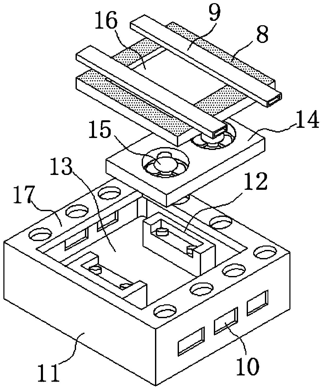
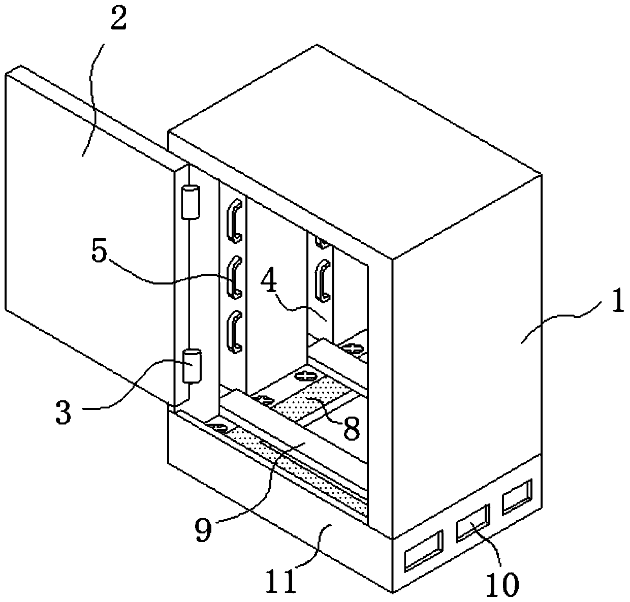
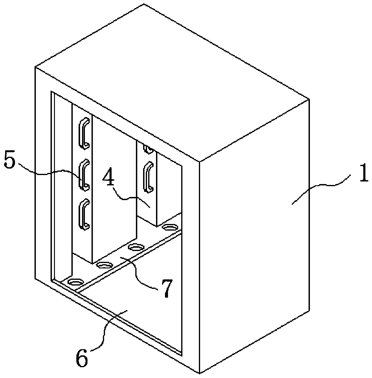
[0022] see Figure 1-5 , the present invention provides a technical solution: a shell structure of a complete set of high and low voltage equipment, including a base 11 and an equipment cabinet 1 arranged on the upper end thereof, the two sides of the base 11 are provided with air intake openings 10, The inner cavity of the base 11 is provided with a groove 13, and the bottom of the groove 13 is provided with a fixed seat 12 arranged symmetricall...


PUM


Abstract

The invention discloses a housing structure of high- and low-voltage complete equipment, and the housing structure comprises a base and an equipment cabinet body arranged at the upper end thereof, thebottom of the groove is provided with fixed seats in front-back symmetry, upper ends of the front and rear fixed seats are provide with a fan mounting plate, front and rear sides of the upper end ofthe fan mounting plate are equipped with two fans, the upper end of the groove is provided with a protective plate, the middle part of the protective plate is provided with a square open through groove, A ventilation plate stretches across the square open through groove, the middle part of the ventilation plate is provided with a ventilation groove, the middle part of the lower end of the ventilation plate is provided with an air inlet communicating with the ventilation groove, when the fans work, part of air enters into the equipment cabinet body through the square open through groove and thesquare opening, thereby providing heat dissipation for components inside the equipment cabinet body, at the same time, the other part of air enters the ventilation groove through the air inlet and finally enters a vertical wiring groove through the two ends of the ventilation plate, thereby dissipating heat for a wire in the vertical wiring groove.

Description

technical field [0001] The invention relates to the technical field of shells of high and low voltage complete sets of equipment, in particular to a shell structure of high and low voltage complete sets of equipment. Background technique [0002] High and low voltage complete sets of equipment include switch cabinets, switchboards, control boxes, switch boxes and other electrical equipment. The power distribution cabinet (box) is divided into power distribution cabinet (box), lighting distribution cabinet (box), metering cabinet (box), and is the final equipment of the power distribution system. The power distribution cabinet is a general term for the motor control center. The power distribution cabinet is used in the occasions where the load is relatively scattered and there are few circuits; the motor control center is used in the occasions where the load is concentrated and there are many circuits. They distribute the electric energy of a certain circuit of the upper-le...

Claims


Application Information

Patent Timeline
Patent Type & Authority Patents(China)
IPC IPC(8): H02B1/30H02B1/56H02B1/20H02B1/38
CPCH02B1/20H02B1/30H02B1/303H02B1/38H02B1/565
Inventor 徐会敏李子乐刘泽楷薛志峰
Owner 刘泽楷
Why Eureka
Try Eureka