A dust-proof and ventilated outdoor power distribution cabinet
A power distribution cabinet, outdoor technology, applied in substation/distribution device housing, substation/switchgear cooling/ventilation, electrical components, etc., can solve the problem of both dustproof and ventilation, and achieve ventilation and dustproof functions Improve, meet the effect of ventilation and heat dissipation, and novel design
- Summary
- Abstract
- Description
- Claims
- Application Information
AI Technical Summary
Problems solved by technology
Method used
Image
Examples
Embodiment 1
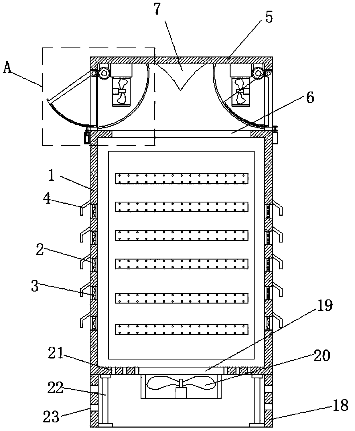
[0024] refer to figure 1 , 2 and 5, a dustproof and ventilated outdoor power distribution cabinet, comprising a main body 1 of the power distribution cabinet, the top of the main body 1 of the power distribution cabinet is provided with a first ventilation device, and the bottom is provided with a second ventilation device, and the main body of the power distribution cabinet 1 is rectangular Hollow structure, and the top is provided with a first ventilation slot 6, the first ventilation device communicates with the main body 1 of the power distribution cabinet through the first ventilation slot 6, and the bottom of the main body 1 of the power distribution cabinet is provided with a second ventilation slot 19, The second ventilation device communicates with the main body 1 of the power distribution cabinet through the second ventilation slot 19. The first ventilation device includes an upper shell 5, which is a rectangular hollow structure and is fixedly welded on the top of t...
Embodiment 2
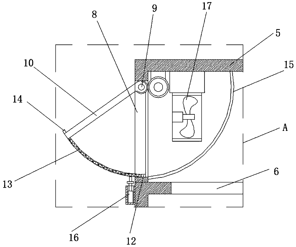
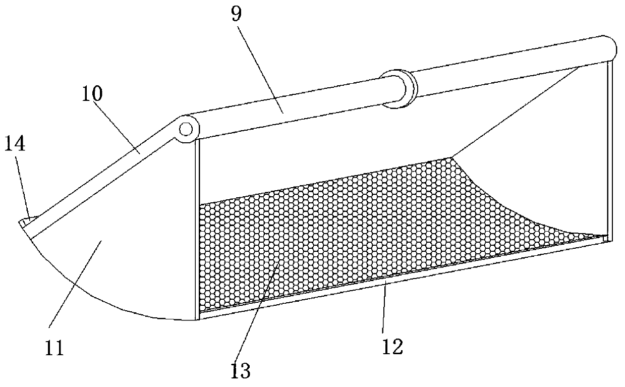
[0027] refer to Figure 1-3, the adjustment mechanism includes a rotating shaft 9, a baffle plate 10, a fan-shaped plate 11, a support rod 12 and an arc-shaped filter plate 13, wherein the rotating shaft 9 is rotatably mounted on the upper side of the first ventilation slot 6, and the baffle plate 10 One side is fixedly connected on the rotating shaft 9, and the two ends of the baffle plate 10 are symmetrically provided with fan-shaped plates 11, and the arc sides of the two fan-shaped plates 11 are fixedly connected with support rods 12 between the ends of the end of the baffle plate 10, and the support rods 12. An arc-shaped filter plate 13 is fixedly installed in the arc-shaped notch formed by the two fan-shaped plates 11 and the baffle plate 10, and arc-shaped guide strips 15 are arranged symmetrically on the inner wall at both ends of the rectangular air inlet 8 in the main body of the power distribution cabinet 1, and The arc-shaped sides of the two fan-shaped plates 11 ...
Embodiment 3
[0030] refer to figure 2 with 4 The cleaning device 16 includes a support base plate 161, two telescopic pillars 162, a number of support springs 163, support bars 164 and a scraper bar 165, wherein the support base plate 161 is fixed on the outer wall of the upper casing 5 by screws, and is located in a rectangular shape. At the lower side of the tuyere 8, the support base plate 161 is provided with installation grooves along its length direction, and the two ends in the installation groove are fixedly provided with telescopic pillars 162, and the installation grooves between the two telescopic pillars 162 are equidistantly provided with several supports. The spring 163, telescopic support 162 and the end of the support spring 163 away from the groove bottom of the installation groove are all fixedly connected to one side of the support bar 164, and the other side of the support bar 164 is provided with a scraper 165 along its length direction, and the support bar 164 is loc...
PUM
 Abstract
Description
Claims
Application Information
 - R&D
- Intellectual Property
- Life Sciences
- Materials
- Tech Scout
- Unparalleled Data Quality
- Higher Quality Content
- 60% Fewer Hallucinations
Browse by: Latest US Patents, China's latest patents, Technical Efficacy Thesaurus, Application Domain, Technology Topic, Popular Technical Reports.
© 2025 PatSnap. All rights reserved.Legal|Privacy policy|Modern Slavery Act Transparency Statement|Sitemap|About US| Contact US: help@patsnap.com


