A multilevel BOOST device

A multi-level and voltage technology, applied in the direction of output power conversion devices, electrical components, and conversion equipment without intermediate conversion to AC, can solve problems such as device overvoltage breakdown, and achieve the effect of avoiding breakdown failure

Active Publication Date: 2018-12-18
SUNGROW POWER SUPPLY CO LTD
View PDF10 Cites 22 Cited by
  • Summary
  • Abstract
  • Description
  • Claims
  • Application Information

AI Technical Summary

Problems solved by technology

[0005] The present invention provides a multi-level BOOST device to solve the problem in the prior art that there is a risk of device overvoltage breakdown at the moment of power-on when the input voltage is low

Method used


Image

  • A multilevel BOOST device
  • A multilevel BOOST device
  • A multilevel BOOST device

Examples


Embodiment Construction

[0057] The following will clearly and completely describe the technical solutions in the embodiments of the application with reference to the drawings in the embodiments of the application. Apparently, the described embodiments are only some of the embodiments of the application, not all of them. Based on the embodiments in this application, all other embodiments obtained by persons of ordinary skill in the art without creative efforts fall within the protection scope of this application.

[0058] The invention provides a multi-level BOOST device to solve the problem in the prior art that there is a risk of device overvoltage breakdown at the moment of power-on when the input voltage is low.

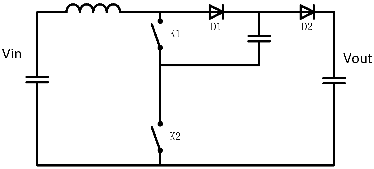
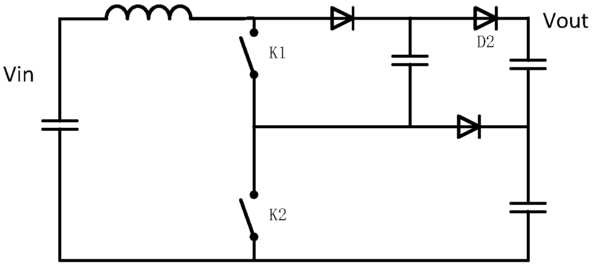
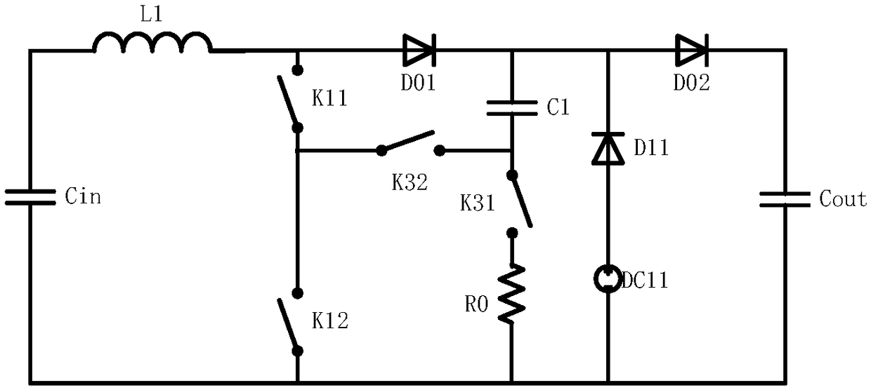
[0059] In practical applications, a multi-level BOOST device generally includes a main circuit, a voltage and current detection device, and a controller; specifically, the main circuit can be as follows: Figure 2a to Figure 2e As shown, including: input capacitor Cin, input inductance L...


PUM


Abstract

The invention provides a multilevel BOOST device, by setting N voltage dividing modules to realize voltage distribution among N first switches, overvoltage of the second to Nth first switches can be avoided and breakdown failure can be avoided. And by subjecting it to the common point between the 1 and the i-th second switch is set to the i-th. 1 clamp branch, so that the voltage applied to the ith second switch is clamped on the difference between the voltage across the fourth branch (i.e., the output voltage of the multilevel BOOST device) and the voltage across the corresponding clamping branch, thereby avoiding the risk of overvoltage breakdown of the second to Nth second switches at the power-on moment when the input voltage is low.

Description

technical field [0001] The invention relates to the technical field of power electronics, in particular to a multi-level BOOST device. Background technique [0002] With the rise of power electronic converter system voltage, the withstand voltage requirements for related switching devices are also gradually increasing. In view of the impact of semiconductor process performance and other aspects, multi-level technology can be realized at a lower cost by using lower voltage level devices. The power change of high voltage has become a research hotspot. [0003] Figure 1a The main circuit topology of a common flying capacitor type three-level BOOST device is shown. Under normal circumstances, the voltage stress of K1, K2, D1 and D2 is half of the output voltage Vout. However, when the circuit is started, the withstand voltage at both ends of each tube is quite different from the steady-state operation. Specifically: if the input voltage Vin is greater than the withstand voltag...

Claims


Application Information

Patent Timeline
Patent Type & Authority Applications(China)
IPC IPC(8): H02M3/08
CPCH02M3/08H02M1/36H02M1/32H02M3/158H02M3/07H02M7/4837H02M1/0061H02M1/0003
Inventor 庄加才徐君张兵王鹏文鹏
Owner SUNGROW POWER SUPPLY CO LTD
Why Eureka
Try Eureka