Electron beam scanning drive control board and electron beam welding machine

A technology of electron beam scanning and drive control, applied in electron beam welding equipment, electrical program control, digital control, etc., can solve the problems of weak anti-interference ability and poor control drive signal accuracy, and achieve improved control accuracy and anti-interference. effect of ability

Active Publication Date: 2021-06-11
河北众航高能科技有限公司
View PDF0 Cites 0 Cited by
  • Summary
  • Abstract
  • Description
  • Claims
  • Application Information

AI Technical Summary

Problems solved by technology

[0006] The purpose of the embodiment of the present invention is to provide an electron beam scanning drive control board and an electron beam welding machine to solve the problems of poor precision of the control drive signal of the scanning coil and weak anti-interference ability in the existing electron beam scanning system

Method used


Image

  • Electron beam scanning drive control board and electron beam welding machine
  • Electron beam scanning drive control board and electron beam welding machine
  • Electron beam scanning drive control board and electron beam welding machine

Examples


Embodiment 1

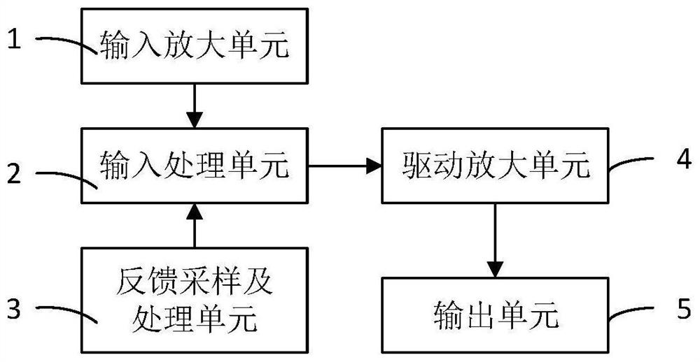
[0035] This embodiment provides an electron beam scanning drive control board for controlling the current of the scanning coil. Such as figure 1 As shown, the electron beam scanning drive control board includes an input amplification unit 1, a feedback sampling and processing unit 2, an input processing unit 3, a driving amplification unit 4 and an output unit 5, and the output terminal of the input amplification unit 1 and the feedback sampling and processing unit 2 The output end of the input processing unit 1 is electrically connected to the input end of the input processing unit 1, the output end of the input processing unit 3 is electrically connected to the input end of the driving amplifying unit 4, and the output end of the driving amplifying unit 4 is electrically connected to the input end of the output unit 5; wherein ,

[0036] The input amplification unit 1 is used to amplify the control input signal; the feedback sampling and processing unit 2 is used to obtain ...

Embodiment 2

[0052] This embodiment provides an electron beam welding machine. Such as Figure 8 and Figure 9 As shown, the electron beam welding machine includes an electron gun 81, an electron beam scanning coil 82, an electron beam scanning drive control board 83 and a signal generator 84. The electron gun 81 is used to emit electron beams, and the electron beam scanning coil 82 is arranged on the The emission path of the electron beam, the signal generator 84 is used to generate a control input signal for controlling the deflection direction of the electron beam, and the electron beam scanning drive control board 83 is used to process the control input signal, and the processed The driving signal is input into the electron beam scanning coil 82, wherein the electron beam scanning driving control board 83 adopts the electron beam scanning driving control board provided in Embodiment 1.

[0053] In this embodiment, the electron beam scanning coil 82 includes an X scanning coil and a Y...


PUM


Abstract

The invention discloses an electron beam scanning drive control board and an electron beam welding machine. The electronic beam scanning drive control board includes an input amplification unit, a feedback sampling and processing unit, an input processing unit, a driving amplification unit and an output unit, the input amplification unit is used to amplify the control input signal; the feedback sampling and processing unit is used Obtaining the actual current value in the scanning coil and transmitting the feedback signal to the input processing unit; the input processing unit is used to perform PID operation on the control input signal and the feedback signal to obtain a driving signal; the driving The amplifying unit is used for amplifying the driving signal obtained by the input processing unit; the output unit is used for outputting the amplified driving signal to the scanning coil. The electronic beam scanning drive control board has high control precision and strong anti-interference ability.

Description

technical field [0001] The invention relates to the technical field of vacuum welding, in particular to an electron beam scanning drive control board and an electron beam welding machine. Background technique [0002] Electron beam welding is the use of spatially oriented high-speed moving electron beams to hit the surface of the workpiece, the kinetic energy of the electrons is converted into heat energy to melt the metal to be welded, and the molten metal cools and crystallizes to form a weld. Electron beam welding has the advantages of high heating power density, large weld depth-to-width ratio, fast welding speed, small heat-affected zone, small welding deformation, high weld purity, wide adjustment range of welding process parameters, strong adaptability and many weldable materials, etc. Many advantages. [0003] The electron beam welding machine used in electron beam welding is a technology-intensive equipment that integrates various high-tech technologies such as vac...

Claims


Application Information

Patent Timeline
Patent Type & Authority Patents(China)
IPC IPC(8): G05B19/18B23K15/02
CPCB23K15/02
Inventor 白凤民
Owner 河北众航高能科技有限公司
Why Eureka
Try Eureka