
Machining driving device with remote controller

A driving device and machining technology, applied in metal processing, metal processing equipment, metal processing mechanical parts, etc., can solve the problems affecting the normal power supply of the driving device, reducing the service life of the driving device, and complicated steps, so as to achieve convenient and fast lubrication. Maintenance, improve service life, ensure the effect of normal supply

Inactive Publication Date: 2018-12-21
宁国市金优机械配件有限公司
View PDF3 Cites 0 Cited by
  • Summary
  • Abstract
  • Description
  • Claims
  • Application Information

AI Technical Summary

Problems solved by technology

[0003] However, in the process of using the driving device, firstly, the internal components vibrate, which affects the normal power supply of the driving device. Secondly, the installed driving device needs to be disassembled and lubricated for maintenance. After maintenance, it must be reinstalled and fixed. The steps are cumbersome. And during the disassembly and installation process, certain damages are caused to the driving device. In addition, when the driving device is not in use, dust and impurities enter the inside of the driving device from the heat dissipation window, which has certain adverse effects on the internal components and reduces the service life of the driving device. Therefore, it is necessary to design a machining driving device with a remote controller to ensure the normal operation of the equipment

Method used

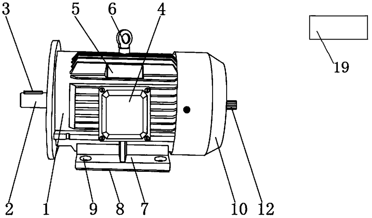
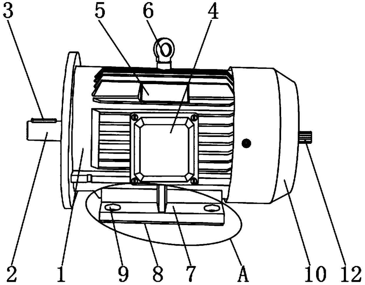
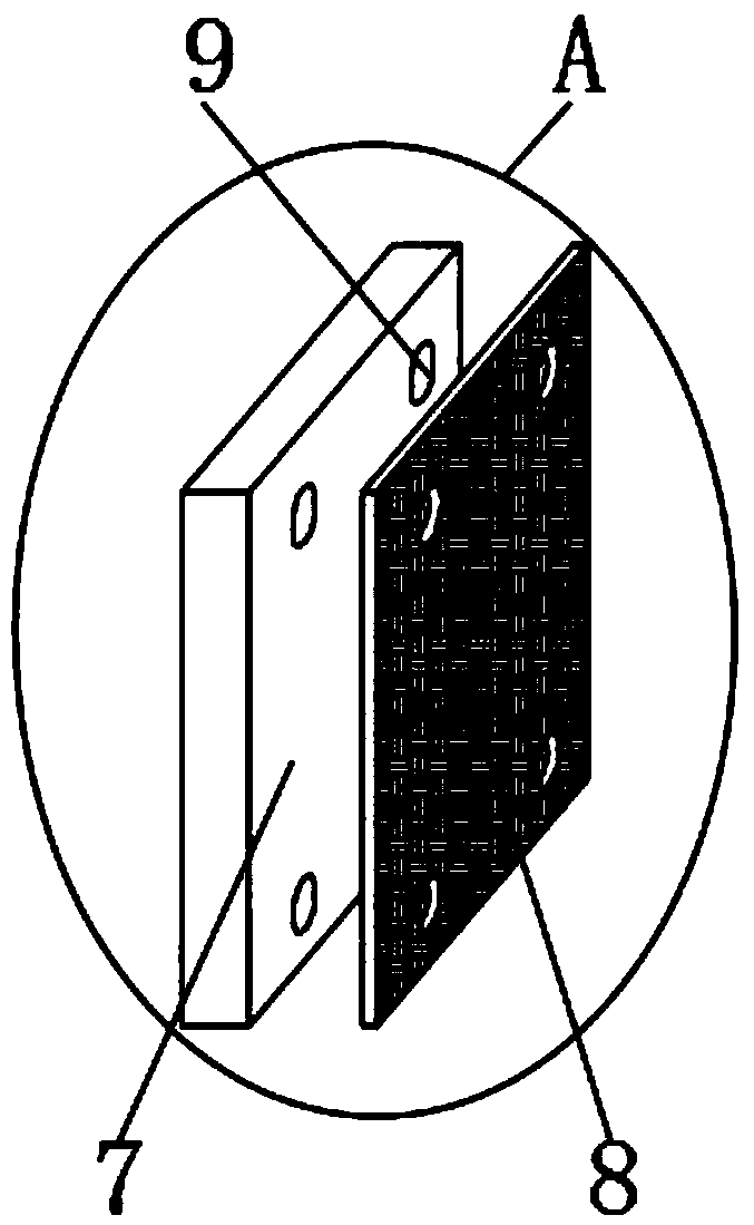

Image

  • Machining driving device with remote controller
  • Machining driving device with remote controller
  • Machining driving device with remote controller

Examples


Embodiment Construction

[0023] Below, the present invention will be further described in conjunction with the accompanying drawings and specific implementation methods. It should be noted that, under the premise of not conflicting, the various embodiments described below or the technical features can be combined arbitrarily to form new embodiments. .

[0024] It should be noted that when a component is said to be "fixed" to another component, it can be directly on the other component or there can also be an intervening component. When a component is said to be "connected" to another component, it may be directly connected to the other component or there may be intervening components at the same time. When a component is said to be "set on" another component, it may be set directly on the other component or there may be an intervening component at the same time. The terms "vertical," "horizontal," "left," "right," and similar expressions are used herein for purposes of illustration only.

[0025] li...


PUM


Abstract

The invention discloses a machining driving device with a remote controller. The machining driving device with the remote controller comprises a driving device shell; the outer surface of one end of the driving device shell is fixedly connected with a driving main shaft; No.2 fixing screw holes and a lubricating oil injection hole are formed in the outer surface of one end of the driving device shell; the No.2 fixing screw holes are positioned in the outer surface of the periphery of the driving main shaft; and the lubricating oil injection hole is formed in one side of the driving main shaft.According to the machining driving device with the remote controller disclosed by the invention, a damping cushion layer, the lubricating oil injection hole and anti-dust blades are arranged, and a certain damping effect can be achieved in long-time operating work of the driving device, so that normal supply of the power of the driving device is ensured, and lubricating oil can be injected at a connecting position of the driving device conveniently and quickly without detaching the driving device; and dust and impurities can also be prevented from entering the device when the driving device is not used, normal work of internal components is protected, and better use prospect is brought.

Description

technical field [0001] The invention relates to the field of driving devices, in particular to a machining driving device with a remote controller. Background technique [0002] With the rapid development of my country's economic construction, most industries are inseparable from mechanical processing, and mechanical processing equipment requires power supply, among which the drive device is an indispensable component. [0003] However, in the process of using the drive device, firstly, the internal components vibrate, which affects the normal power supply of the drive device. Secondly, the installed drive device needs to be disassembled and lubricated for maintenance. After maintenance, it must be reinstalled and fixed. The steps are cumbersome. And during the disassembly and installation process, the drive device will be damaged to some extent. In addition, when the drive device is not in use, dust and impurities enter the drive device from the heat dissipation window, whi...

Claims


Application Information

Patent Timeline
Patent Type & Authority Applications(China)
IPC IPC(8): B23Q1/72B23Q5/00B23Q11/12
CPCB23Q1/72B23Q5/00B23Q11/12
Inventor 刘闻
Owner 宁国市金优机械配件有限公司
Learn More