
Cutting knife for die cutting

A cutting knife and die-cutting technology, which is applied in metal processing and other directions, can solve the problems of cutting tool cost waste, cutting knife scrapping, and small knife edge angle, etc., to save tool cost, prevent jamming or breaking, and prolong service life. Effect

Inactive Publication Date: 2018-12-21
FOSHAN KUIFENG BUSINESS CONSULTATION SERVICES CO LTD
View PDF0 Cites 2 Cited by
  • Summary
  • Abstract
  • Description
  • Claims
  • Application Information

AI Technical Summary

Problems solved by technology

[0005] 1. The general die-cutting cutter has an integrated structure. After a long time of rolling die-cutting, once the blade is damaged, it must be replaced with a new cutter, which wastes the cost of the cutter.
[0006] 2. The cutting edge angle of the general cutting knife for die cutting is small. The smaller the edge angle, the smaller the die cutting resistance, which is naturally sharper and easier to cut through. However, the smaller the edge angle, the guarantee of its sharpness and cutting edge The more difficult the correct broaching process is, the easier it is for the tip to be blunted or broken, and the entire cutting knife will be scrapped, which is also a great waste of tool cost

Method used


Image

  • Cutting knife for die cutting
  • Cutting knife for die cutting
  • Cutting knife for die cutting

Examples


Embodiment 1

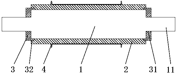
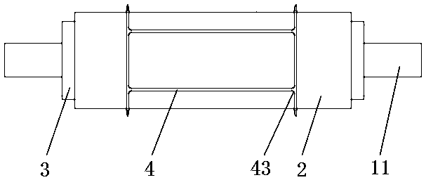
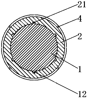
[0030] Example 1, see Figure 1-4 , the present invention provides a technical solution: a cutting knife for die-cutting, including a roller 1, a knife sleeve 2, a shaft sleeve 3 and a blade 4, the roller 1 is a cylindrical structure, and the two sides of the roller 1 A roller shaft 11 is provided, and the outer wall of the roller 1 is evenly fixed with six bumps 12, the bumps 12 are strip-shaped structures, and the length of the bumps 12 is 4 / 5 of the length of the roller 1, so The protrusion 12 is parallel to the axis of the roller 1, and the outer wall of the roller 1 is provided with first threads 13 on both sides.

[0031] The outer side of the roller 1 is movably connected with a knife cover 2, the knife cover 2 is a cylindrical structure, and the inner wall of the knife cover 2 is uniformly provided with a groove 21 matching the bump 12, and the knife cover 2 passes through the The groove 21 and the protrusion 12 are slidably connected with the roller 1, which facilita...

Embodiment 2

[0036] Example 2, see Figure 7 , the present invention provides a technical solution: a cutting knife for die-cutting, including a roller 1, a knife sleeve 2, a shaft sleeve 3 and a blade 4, the roller 1 is a cylindrical structure, and the two sides of the roller 1 A roller shaft 11 is provided, and a second thread 14 is evenly opened in the middle of the outer wall of the roller 1, and the length of the second thread 14 is 4 / 5 of the length of the roller 1, and the roller 1 passes through the second thread. 14 is threadedly connected with the tool holder 2, and first threads 13 are provided on both sides of the outer wall of the roller 1.

[0037] see Figure 1-3 The outer side of the roller 1 is movably connected with a knife cover 2, the knife cover 2 is a cylindrical structure, and the inner wall of the knife cover 2 is uniformly provided with a groove 21 matching the bump 12, and the knife cover 2 passes through the The groove 21 and the protrusion 12 are slidably conn...


PUM

PropertyMeasurementUnit
Thicknessaaaaaaaaaa
Height dimensionaaaaaaaaaa

Abstract

The invention discloses a cutting knife for die cutting. The cutting knife comprises a roll wheel, a knife sleeve, a shaft sleeve and a cutting edge. The roller is of a cylindrical structure. Rollersare arranged on the two sides of the roll wheel. The outer side of the roll wheel is movably connected with a knife sleeve. The knife sleeve is of a cylindrical structure. The cutting edge is fixed tothe outer side of the knife sleeve. A joint of the cutting edge is provided with a rounded corner. The two sides of the roll wheel are in threaded connection with the shaft sleeve. By uniformly fixing protrusion blocks on the outer wall of the roll wheel, the inner wall of the knife sleeve is uniformly provided with grooves matched with the protrusion blocks, the knife sleeve is slidably connected with the roll wheel through the grooves and the protrusion blocks, the cutting edge is fixed to the outer side of the knife sleeve, if the cutting edge is damaged, the knife sleeve can be replaced convenient and directly, the roll wheel is reused, and the knife cost is reduced. By setting the cutting nose angle of the cutting edge formed by a first oblique side to be 50 degrees, the cutting edgeangle is large enough so that parts can be easily cut through, jamming or breaking is avoided, the cutting edge cutting nose is quenched, and the service life of the cutting knife is prolonged.

Description

technical field [0001] The invention relates to the technical field of die-cutting knives, in particular to a cutting knife for die-cutting. Background technique [0002] Traditional die-cutting refers to a cutting process in the post-processing of printed matter. The die-cutting process can make printed matter or other paper products into a die-cutting knife plate for cutting according to the pre-designed graphics, so that the shape of the printed matter is no longer Limited to straight sides and right angles. Traditional die-cutting production uses a die-cutter to form a die-cutting plate according to the pattern required by the product design. Under the action of pressure, the printed matter or other plate-like blanks are rolled and cut into the required shape or cut. [0003] At present, the rotary die-cutting is line contact, the die-cutting pressure is small, the equipment power is small, the stability is good, the continuous rolling die-cutting is high, the productio...

Claims


Application Information

Patent Timeline
IPC IPC(8): B26F1/44B26D7/26
CPCB26F1/44B26D7/2614B26F2001/4472
Inventor 不公告发明人
Owner FOSHAN KUIFENG BUSINESS CONSULTATION SERVICES CO LTD
Learn More