Fixed-shaft roughing method for integral impeller

An integral, impeller technology, applied in the details of milling machine equipment, metal processing equipment, milling machine equipment, etc., can solve the problems of low cutting efficiency, rising tool cost, shortening tool life, etc., and achieve the effect of improving processing efficiency and reducing tool cost.

Pending Publication Date: 2022-01-28
CHONGQING JIANGJIN SHIPBUILDING IND
View PDF0 Cites 0 Cited by
  • Summary
  • Abstract
  • Description
  • Claims
  • Application Information

AI Technical Summary

Problems solved by technology

This processing method cannot fully utilize the side edge of the tool, and the cutting efficiency is low, and the small and constant cutting depth of each tool will cause concentrated wear on the front end of the tool, shorten the tool life, and increase the cost of the tool.

Method used


Image

  • Fixed-shaft roughing method for integral impeller
  • Fixed-shaft roughing method for integral impeller
  • Fixed-shaft roughing method for integral impeller

Examples


Embodiment Construction

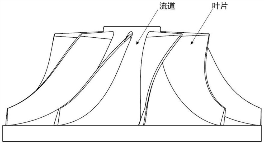
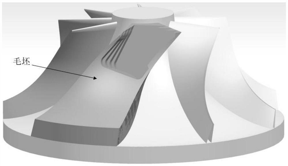
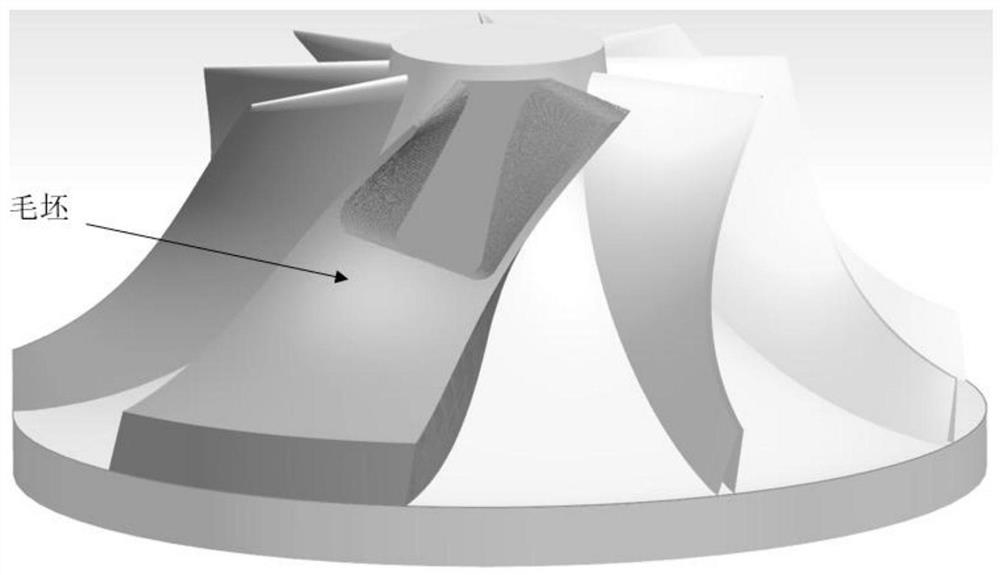
[0028] See Figure 1 - Figure 4 , Fixed axis A monolithic impeller roughing embodiment of a method.

[0029] The main fixed axis roughing step: Set the cutter shaft is oriented geometry → → → long edge a coarse setting parameter generating program → → → Duanren two crude → generator setting parameters. Unlike the prior art in that: the process will have to use the long edge and short edge knife blade machining two knives, a knife in the same orientation axes, the first for the first in the current view of a long edge milling cutter a rough, after completion of a most rough balance, and then subjected to a second short edge rough milling cutter, to complete the removal of remaining in the current view, these two are performed in the same rough milling cutter axis at a second time the crude when milling is blank after completion of the first impeller roughing.

[0030] The present invention is different from the prior art in that: the process will have to use the long edge and short ...


PUM

PropertyMeasurementUnit
Blade diameteraaaaaaaaaa
Blade lengthaaaaaaaaaa

Abstract

The invention discloses a fixed-shaft roughing method for an integral impeller. The fixed-shaft roughing method is more efficient and economical. The method comprises the following steps: S1, establishing a geometric model of the integral impeller; s2, setting cutter shaft orientation; s3, in the set cutter shaft orientation, setting a long-edge cutter for first-time rough milling, setting machining parameters, generating a machining program, and completing most rough machining allowance through first-time rough machining; s4, in the same set cutter shaft orientation, setting a short-edge cutter for second-time rough milling, setting machining parameters, generating a machining program, and removing the remaining rough machining allowance through secondary rough machining; the cutting depth of the second short-edge cutter is smaller than that of the first long-edge cutter, the cutting step pitch of the second short-edge cutter is larger than that of the first long-edge cutter, the cutter rotating speed of the second short-edge cutter is smaller than that of the first long-edge cutter, and the feeding speed of the second short-edge cutter is smaller than that of the first long-edge cutter; and S5, rotating the impeller to the next machining area, and repeating the steps S2-S9 till rough machining of the integral impeller is completed.

Description

Technical field [0001] The present invention relates to the technical field of mechanical machining, particularly to a monolithic impeller fixed axis roughing method. Background technique [0002] Compressor impeller is integral core member turbomachinery, milling is often used. Wherein the proportion of the processing time of the longest roughing wheel. In conventional monolithic compressor wheels fixed axis roughing, each using only one machining tool oriented generally monolithic indexable end mill or milling cutter, the tool depth of cut of each blade is small and a fixed value, this value is much less than the tool cutting edge length, in particular monolithic mill. This processing method can not fully utilize the side edge of the tool, the cutting efficiency is low, and each blade is small and constant cutting depth will cause the front end of the focus tool wear, shortened tool life, machining cost of the tool is increased. [0003] Prior art fixed axis roughing main steps...

Claims


Application Information

Patent Timeline
IPC IPC(8): B23C3/00
CPCB23C3/00B23C2220/60
Inventor 赵举坤鲁建于袁列军吴琳罗攀赵倩邹含青邓欣卢常鑫
Owner CHONGQING JIANGJIN SHIPBUILDING IND
Why Eureka
Try Eureka