
Charging pile

A charging pile and charging gun technology, used in electric traction, electric vehicles, transportation and packaging, etc., can solve the problems of easy theft, shortened service life, and the gun wire is susceptible to ground friction, so as to avoid damage and extend the Longevity and effect of reducing the chance of theft

Active Publication Date: 2018-12-21
正星科技股份有限公司
View PDF5 Cites 8 Cited by
  • Summary
  • Abstract
  • Description
  • Claims
  • Application Information

AI Technical Summary

Problems solved by technology

[0005] The invention proposes a charging pile, which solves the problem that the gun line is easily subject to ground friction, resulting in shortened service life or easy theft

Method used


Image

  • Charging pile
  • Charging pile
  • Charging pile

Examples


Embodiment 1

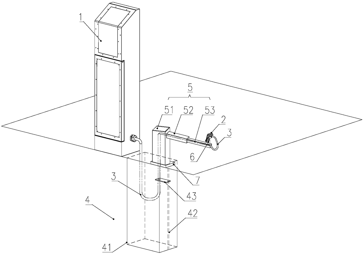
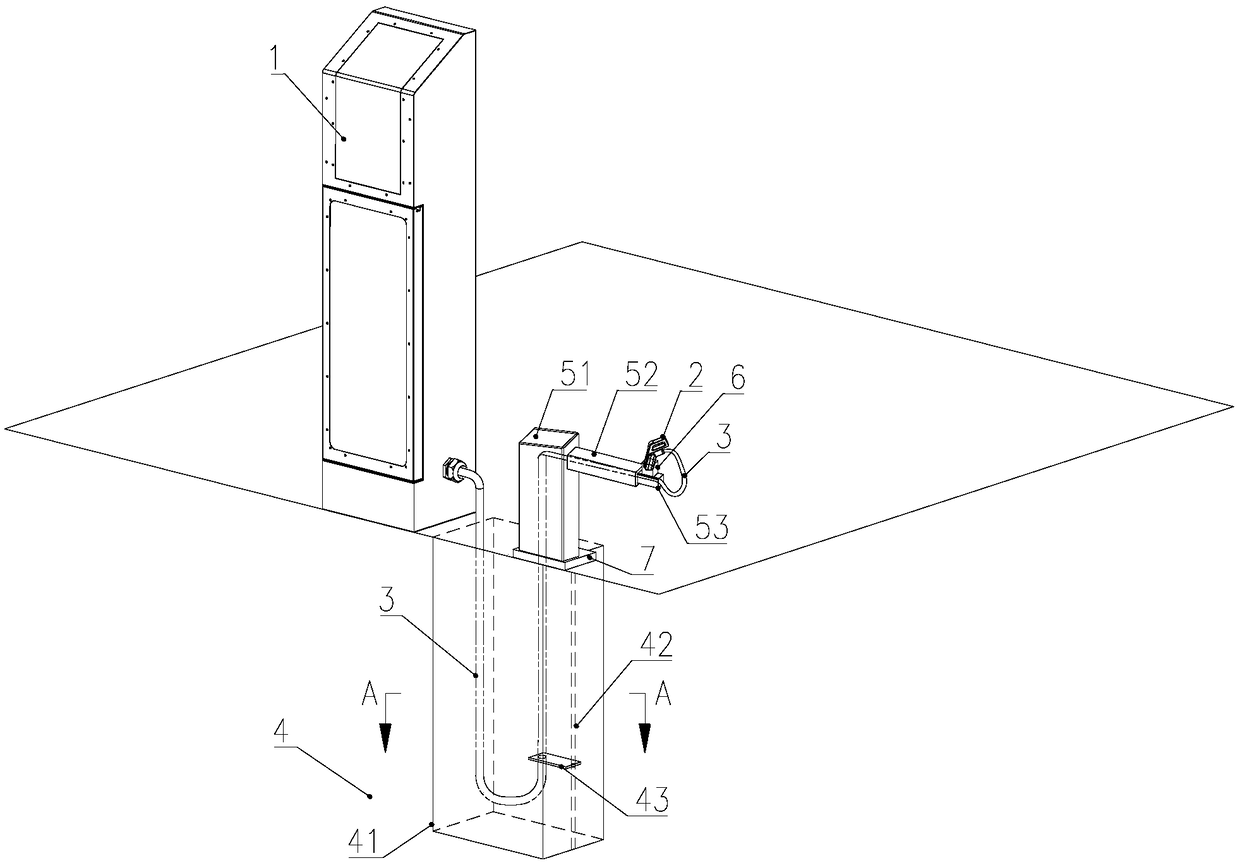
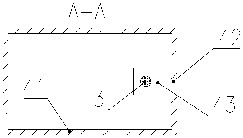
[0046] Such as figure 1 , figure 2 As shown, a charging pile includes a charging pile 1, a charging gun 2, and a charging wire 3. One end of the charging wire 3 is connected to the charging pile 1, and the other end is connected to the charging gun 2. The charging pile also includes a charging wire. The retractable device 4 and the bracket 5; wherein, the sliding device 43 is equipped with control equipment; the charging gun 2 is provided with an induction device, and the induction device is linked with the control equipment; the gun wire retractable device 4 is buried in Under the ground, it is used to store or release the gun wire 3; the bracket 5 is placed on the ground, and used to support the gun wire 3.

[0047] Such as Figure 4 As shown, the support 5 includes a vertical pole 51 arranged on the ground, a fixed pole 52 vertically connected with the vertical pole 51, and one or more movable poles 53, and the movable pole 53 is nested and connected with the fixed pole ...

Embodiment 2

[0063] The structural difference between this embodiment and Embodiment 1 is that, as Image 6 As shown, the gun wire supporting device is an electric winch 44 arranged at the bottom of the box body 41, instead of the chute 42 arranged on the surrounding wall of the box body 41 in Embodiment 1 and the slide that can move up and down along the chute 42 The device 43 is suitable for reducing the height of the box 41 in some places where it is not convenient to dig deep and bury the box 41, and only need to excavate the shallow ground to realize its anti-theft function; wherein, the electric winch 44 is equipped with There is control equipment; the charging gun 2 is provided with an induction device, and the induction device is linked with the control equipment.

[0064] In this embodiment, the working process of the charging pile 1 is as follows:

[0065] When the electric vehicle needs to be charged, the user parks the electric vehicle near the bracket 5, and conducts pre-char...


PUM


Abstract

The invention relates to the field of charging piles, in particular to a charging pile, comprising a charging pile, a charging gun and a gun wire, wherein one end of the gun wire is connected with thecharging pile and the other end is connected with the charging gun, and the charging pile further comprises a gun wire retracting and placing device and a bracket; Wherein the sliding device is provided with a control device; A sensing device is arranged on the charging gun, and the sensing device is linked with a control device; The gun wire receiving and releasing device is buried under the ground for storing or releasing the gun wire; The bracket is arranged on the ground for supporting the gun wire; The gun thread receiving and placing device of the invention is buried under the ground, and the bracket is seamless all-metal structure, so that it is difficult for the thief to dismantle the gun thread, and the stolen probability is reduced; By means of the control device and the induction device, the automatic retracting and placing of the gun wires is realized, the process of the user dragging the gun wires is avoided, the damage of the gun wires due to friction is reduced, or theforce at the interface between the charging gun and the gun wires due to the dragging is increased, and the service life of the charging gun and the gun wires is prolonged.

Description

technical field [0001] The invention relates to the field of charging piles, in particular to a charging pile. Background technique [0002] With the development and use of clean energy, the electric vehicle market is gradually increasing, and the distribution of charging piles is becoming more and more extensive. Type or wall-mounted type, since the charging pile is a certain distance from the parking space of the electric vehicle, it is necessary to set a certain length of gun line to meet the charging needs. [0003] At present, the gun wire is usually manually wound and hung on the charging pile or directly placed on the ground. When it needs to be used, the operator manually drags and moves the gun wire close to the charging port. This kind of operation method has the following problems: 1. The gun wire has a certain Length, random winding or hanging are prone to knotting and winding. On the one hand, it is easy to cause the twisting of the gun line, and the long-term ...

Claims


Application Information

Patent Timeline
Patent Type & Authority Applications(China)
IPC IPC(8): B60L11/18
Inventor 郑永坤
Owner 正星科技股份有限公司
Learn More