
Paper bowl automatic collection device

An automatic collection and paper bowl technology, applied in the directions of transportation and packaging, conveyor objects, etc., can solve the problem that the paper bowls cannot be counted, stacked and sub-packed, the cup collection cannot be carried out continuously, and the stacking and collection quality of paper bowls cannot be well guaranteed. question

Pending Publication Date: 2018-12-21
ZHEJIANG NEW DEBAO MACHINERY
View PDF0 Cites 0 Cited by
  • Summary
  • Abstract
  • Description
  • Claims
  • Application Information

AI Technical Summary

Problems solved by technology

[0002] For some paper bowls with a large ratio of bowl mouth diameter / bowl height, if a circular cup collection pipe is used to transport the cup before collection, the paper bowl will easily roll over due to uneven force under the action of wind blowing. The tumbling paper bowls cannot be counted, stacked and divided in the collection device; if a square cup collection pipeline is used to transport them, although the paper bowls will not roll over, according to the existing cup collection method, the cup collection mouth is located at the collection point. On the top of the cup cage, it is necessary to design a complex steering mechanism to complete the 90-degree turn of the paper bowl before collecting it, which seriously affects the production speed; in addition, when the cup cage is opened to discharge the cups, there is no Collect the cups, and the cup collection work cannot be carried out continuously
And the paper bowl collecting device of prior art, paper bowl is easy to be bruised in the collection process, can't guarantee the stacking collection quality of paper bowl well

Method used


Image

  • Paper bowl automatic collection device
  • Paper bowl automatic collection device
  • Paper bowl automatic collection device

Examples


Embodiment Construction

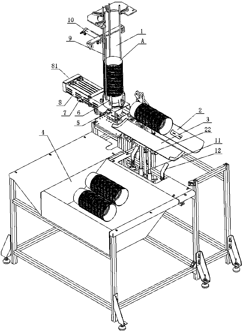
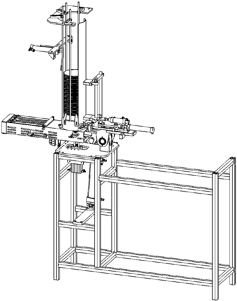
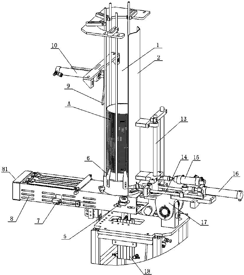
[0019] As shown in the figure, the automatic collection device for paper bowls of the present invention includes a cup collection enclosure 1, which has a cup collection opening 20, and the cup collection opening 20 is located at the bottom of the cup collection enclosure 1 (see Figure 5 ), there is a cup collector 8 under the cup collector 1, the cup collector 8 has a square lumen, and the bottom of the cup collector 8 is provided with a bowl pushing cylinder 18 to push the paper bowl 8 in the cup collector upwards into the cup collector. The cup enclosure cage 1, the top of the push rod of the bowl pushing cylinder 18 is connected to the bowl pushing block 19, the side of the cup collector 8 is provided with a cup connecting port 81 connected to the cup collecting pipeline, and the cup connecting port 81 is also square to connect the square cup collecting Pipeline, the front side of the cup receiver 8 is provided with a first optical eye 7 and a second optical eye 5, the fir...


PUM


Abstract

The invention discloses a paper bowl automatic collection device. The paper bowl automatic collection device comprises a cup collecting enclosure basket; a cup collection opening is formed in the cupcollecting enclosure basket; an enclosure plate is arranged on one side of the cup collecting enclosure basket; the enclosure plate is connected to a turnover frame; the turnover frame can turn over downwards and is pushed by a downward turnover cylinder; the paper bowl automatic collection device is characterized in that the cup collection opening is formed in the bottom of the cup collecting enclosure basket; a cup collector is arranged under the cup collecting enclosure basket; a bowl pushing cylinder is arranged at the bottom of the cup collector to push a paper bowl in the cup collector into the cup collecting enclosure basket upwards; a cup receiving opening connected with a cup collection pipeline is formed in one side of the cup collector; multiple elastic sheets are arranged in the position, close to the bottom, of the cup collecting enclosure basket; and the multiple elastic sheets mutually enclose a circumferential space whose diameter is smaller than the external diameter of a paper bowl opening. According to the paper bowl automatic collection device, vertically conveyed paper bowls can be collected in the cup collecting pipeline at a high speed and can be continuouslycollected; and moreover, the paper bowl is prevented from being damaged while being hit; and the paper bowl stacking and collecting quality is guaranteed.

Description

technical field [0001] The invention relates to a paper cup or paper bowl forming machine, in particular to an automatic collecting device of the paper cup or paper bowl forming machine. Background technique [0002] For some paper bowls with a large ratio of bowl mouth diameter / bowl height, if a circular cup collection pipe is used to transport the cup before collection, the paper bowl will easily roll over due to uneven force under the action of wind blowing. The tumbling paper bowls cannot be counted, stacked and divided in the collection device; if a square cup collection pipeline is used to transport them, although the paper bowls will not roll over, according to the existing cup collection method, the cup collection mouth is located at the collection point. On the top of the cup cage, it is necessary to design a complex steering mechanism to complete the 90-degree turn of the paper bowl before collecting it, which seriously affects the production speed; in addition, wh...

Claims


Application Information

Patent Timeline
IPC IPC(8): B65G47/248
CPCB65G47/248
Inventor 戴道金彭自良黄友余周建修
Owner ZHEJIANG NEW DEBAO MACHINERY
Learn More