Automatic tension balancing device

A tension balance device and automatic technology, which is applied in the directions of transportation and packaging, delivery of filamentous materials, thin material processing, etc., can solve the problems of centrifugal force of the pay-off reel, lack of balance measures, and disordered cable winding, etc., to achieve Avoid the effects of centrifugal force rejection, avoid winding disorder, and prevent winding disorder

Pending Publication Date: 2018-12-21
HEFEI SMARTER TECH GROUP CORP
View PDF0 Cites 0 Cited by
  • Summary
  • Abstract
  • Description
  • Claims
  • Application Information

AI Technical Summary

Problems solved by technology

[0003] The purpose of the present invention is to provide an automatic tension balance device, which can solve the situation that the winding wires are disordered or even broken due to unbalanced tension when the traditional wire-releasing and wire-winding equipment is in operation, and Due to the lack of balance measures, it is easy to cause the problem that the centrifugal force is thrown out when the pay-off reel is rotating.

Method used


Image

  • Automatic tension balancing device
  • Automatic tension balancing device

Examples


Embodiment Construction

[0021] The technical solutions of the present invention will be clearly and completely described below in conjunction with the embodiments. Apparently, the described embodiments are only some of the embodiments of the present invention, not all of them. Based on the embodiments of the present invention, all other embodiments obtained by persons of ordinary skill in the art without creative efforts fall within the protection scope of the present invention.

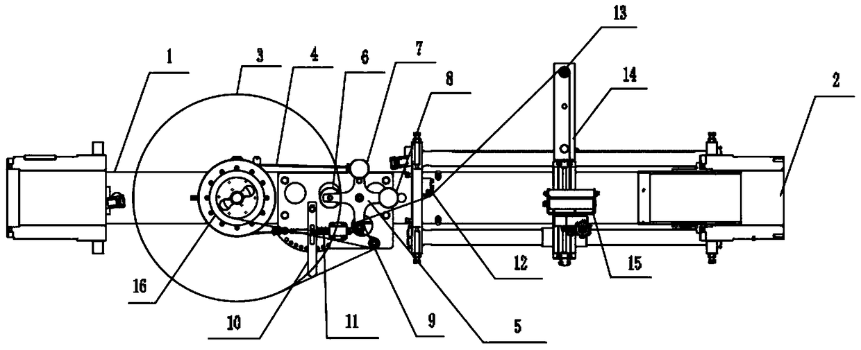
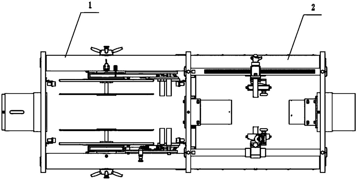
[0022] see Figure 1-2 As shown, an automatic tension balance device includes a pay-off frame 1 and a winding frame 2 connected thereto. 1 The top is equipped with a tape release reel 3, which is used to release the conveyor belt that drives the winding bag 16 to rotate. 3. A cross balance frame 5 is installed on one side, and a second counterweight 7 and a third counterweight 8 are respectively installed on the tops of the two adjacent ends of the cross balance frame 5. The cross balance frame 5 is connected to the second...


PUM


Abstract

The invention discloses an automatic tension balancing device. The problems that during operating of traditional paying-off and winding equipment, winding disorder or even cable breaking due to unbalanced tension of a wound cable is prone to occurring frequently, and in addition, because of a lack of balancing measures, a paying-off bobbin is prone to being rotated backwards under centrifugal force during rotating can be solved. The automatic tension balancing device comprises a paying-off frame and a winding frame connected with the paying-off frame. A belt paying-off disc is mounted at the top of the paying-off frame. A tension belt is arranged at the bottom of the belt paying-off disc in a traction mode. A lapping head is mounted on the belt paying-off disc, and a cross-shaped balancingsupport is mounted on one side of the belt paying-off disc. A second balancing weight and a third balancing weight are mounted at the tops of the adjacent two ends of the cross-shaped balancing support correspondingly. When the device works, the situation that the distances between guide rollers and a turning roller are excessively long, the cable is loosened, and consequentially, wound cable disorder is caused can be prevented, in addition, the weight of the three balance weights on the cross-shaped balancing support is equal to the weight of the guide rollers, and therefore, the lapping head can be prevented from being rotated backwards during rotating.

Description

technical field [0001] The invention relates to a tension balance device, in particular to an automatic tension balance device. Background technique [0002] Whether it is a wire drawing machine or a wire twisting machine, it needs to be equipped with wire-releasing and winding equipment during operation, and the wire-releasing and winding equipment often causes winding disorder due to unbalanced tension of the wound cables during operation. Even breakage, and due to the lack of balance measures, it is easy to cause the centrifugal force to be thrown when the pay-off reel is rotating. Contents of the invention [0003] The purpose of the present invention is to provide an automatic tension balance device, which can solve the situation that the winding wires are disordered or even broken due to unbalanced tension when the traditional wire-releasing and wire-winding equipment is in operation, and Due to the lack of balance measures, it is easy to cause the problem that the ...

Claims


Application Information

Patent Timeline
Patent Type & Authority Applications(China)
IPC IPC(8): B65H59/36B65H57/14
CPCB65H59/36B65H57/14B65H2701/36
Inventor 何金龙倪振
Owner HEFEI SMARTER TECH GROUP CORP
Why Eureka
Try Eureka