Folding-type grain pile pedal

A folding, pedal technology, applied in roads, special pavements, roads, etc., can solve problems such as slipping and pedals are difficult to move, and achieve the effect of easy use, convenient movement and storage, and not easy to slip

Pending Publication Date: 2018-12-21
王芳
View PDF0 Cites 0 Cited by
  • Summary
  • Abstract
  • Description
  • Claims
  • Application Information

AI Technical Summary

Problems solved by technology

At present, in order to avoid sinking when used on grain piles, the pedal for viewing grain is usually designed as a whole panel. Because it is a whole panel, it is difficult to move the pedal conveniently, and the panel is easy to slide on the grain surface, making people possible slipping

Method used


Image

  • Folding-type grain pile pedal
  • Folding-type grain pile pedal
  • Folding-type grain pile pedal

Examples


Embodiment 1

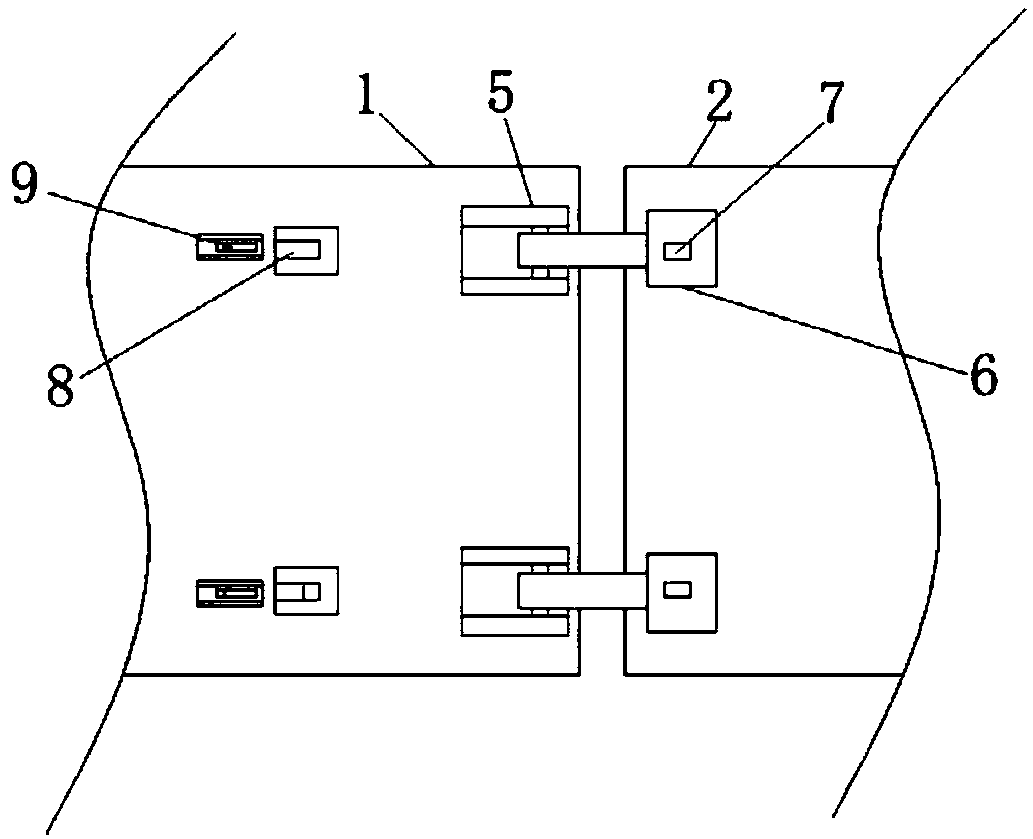
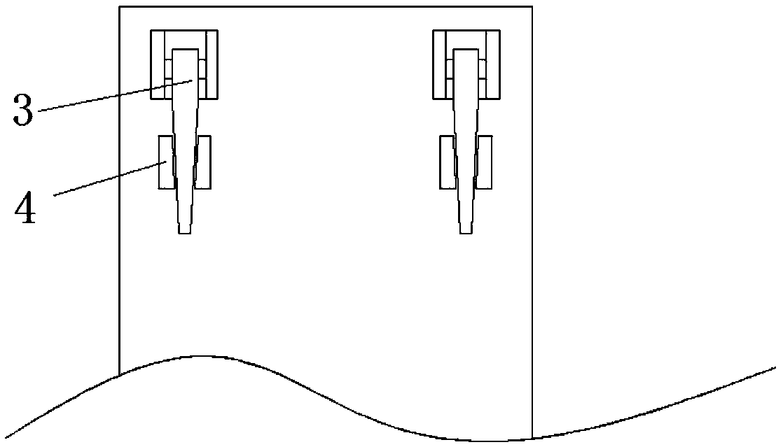
[0029] refer to Figure 1-5 , a foldable grain pile pedal, used on the grain pile to facilitate managers to walk on the grain pile, the pedal includes a first pedal 1 and a second pedal 2, the length and width of the first pedal 1 and the second pedal 2 are the same The bottom ends of the first pedal 1 and the second pedal 2 are all rotatably equipped with a rotating rod 3, and the bottom ends of the first pedal 1 and the second pedal 2 are all fixed with a rotating seat 13 (combined with Figure 6 and Figure 7 ), the rotating rod 3 passes through the rotating shaft 14 (combined with Figure 6 and Figure 7 ) is rotatably connected with the rotating seat 13, one side of the rotating rod 3 is provided with a block 4, and the block 4 is fixedly connected with the bottom ends of the first pedal 1 and the second pedal 2, and the bottom end of the block 4 is provided with a first Draw-in slot, rotating rod 3 is positioned in the first draw-in groove, and the bottom end of rotat...

Embodiment 2

[0032] The difference from Example 1 is that the combination Figure 6 and Figure 7 As shown, in this embodiment, an elastic block 15 is fixedly connected to the top of the rotating rod 3, such as sticking, the elastic block 15 is elastic and can be deformed. When the elastic block 15 is in a non-compressed state, the longitudinal length of the elastic block 15 is greater than that of the rotating rod. 3 The distance between the top end and the bottom end of the first pedal 1, the longitudinal length of the elastic block 15 is greater than the distance between the top end of the rotating rod 3 and the bottom end of the second pedal 2, so that the rotating rod 3 is rotated so that the rotating rod 3 and the first pedal 1 is perpendicular to the second pedal 2, and the elastic block 15 is deformed and compressed, so that the rotating rod 3 is in contact with the first pedal 1 and the second pedal 2. During use, the rotating rod 3 is not easy to rotate in position, ensuring safe...

Embodiment 3

[0035] The difference from Example 2 is that the combination Figure 8 and Figure 9 As shown, the first pedal 1 and the second pedal 2 of this embodiment are all provided with a first receiving groove 16 with the opening facing upwards, and the opening of the first receiving groove 16 is provided with a first sealing cover 26, and the first sealing cover 26 is threaded. Connected to the first receiving groove 16, and the top of the first sealing cover 26 is flush with the tops of the first pedal 1 and the second pedal 2, the bottom of the first receiving groove 16 is provided with a first opening, and the first receiving groove 16 A first spring 17 and a first limiting post 18 are provided inside, and the first spring 17 and the first limiting post 18 are arranged sequentially from top to bottom. The top of the first limiting post 18 is provided with a first limiting shoulder 19, One end of the first spring 17 abuts against the first sealing cover 26, the other end of the fi...


PUM


Abstract

The invention discloses a folding grain pile pedal, includes a first pedal and a second pedal, the bottom end of the first pedal and the bottom end of the second pedal are both rotatably mounted witha rotating bar, A mounting block is fixedly connected to a side of a top end of the first pedal close to the second pedal, a top end of the second pedal is fixedly connected with a fixing block on a side adjacent to the first pedal, A side of the fixing block close to the mounting block is rotatably connected with the mounting block, and the top end of the fixing block is fixedly connected with aclamp hook, the top end of the first pedal is provided with a second card groove, A sliding hole is formed on the inner wall of the second clamping groove on the side away from the second pedal, a clamping rod arranged horizontally is slidably installed in the sliding hole, a spring arranged horizontally is fixedly connected between the clamping rod and the inner wall of the side away from the second pedal, a sliding port is formed on the top end of the first pedal, and a toggle bar is fixedly connected on the top end of the clamping rod. The invention can be stably placed on the grain pile, is not easy to slip, and can be folded up when not in use.

Description

technical field [0001] The invention relates to the technical field of grain storage, in particular to a foldable grain pile pedal. Background technique [0002] The granary is full of grain, and it is used for the convenience of managers to walk on the grain pile in the grain storage, and a pedal is usually laid on the grain pile. At present, in order to avoid sinking when used on grain piles, the pedal for viewing grain is usually designed as a whole panel. Because it is a whole panel, it is difficult to move the pedal conveniently, and the panel is easy to slide on the grain surface, making people Slips and falls are possible. Contents of the invention [0003] The purpose of the present invention is to propose a folding grain pile pedal in order to solve the shortcomings in the prior art. [0004] In order to achieve the above object, the present invention adopts the following technical solutions: [0005] A folding grain pile pedal, comprising a first pedal and a s...

Claims


Application Information

Patent Timeline
Patent Type & Authority Applications(China)
IPC IPC(8): E01C9/08
CPCE01C9/08
Inventor 王芳王鹏
Owner 王芳
Why Eureka
Try Eureka