
Visible light equipment operating distance testing method based on controllable objective target

A technology of working distance and test method, which is applied in the direction of testing optical performance, etc., to achieve the effect of shortening the test cycle, reducing the difficulty of test implementation, and reducing the difficulty of implementation

Inactive Publication Date: 2018-12-21
HENAN UNIV OF SCI & TECH
View PDF5 Cites 7 Cited by
  • Summary
  • Abstract
  • Description
  • Claims
  • Application Information

AI Technical Summary

Problems solved by technology

By changing the size of the controllable target, the contrast of light and dark stripes and the number of cycles, it overcomes the problems of the influence of atmospheric visibility, the limitation of the test site's visibility conditions, and the difficulty of obtaining special targets, and effectively improves the accuracy and operability of the distance test of visible light equipment. sex

Method used


Image

  • Visible light equipment operating distance testing method based on controllable objective target
  • Visible light equipment operating distance testing method based on controllable objective target
  • Visible light equipment operating distance testing method based on controllable objective target

Examples


Embodiment Construction

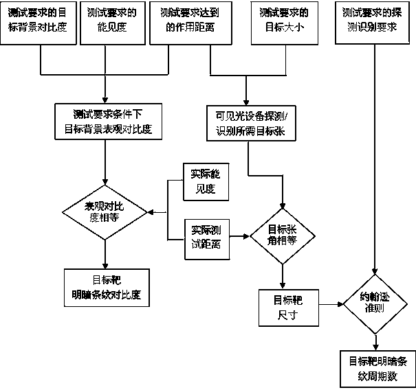
[0028] The embodiments of the present invention will be described in detail below in conjunction with the accompanying drawings. This embodiment is based on the technical solution of the present invention, and provides detailed implementation methods and specific operating procedures, but the scope of protection of the present invention is not limited to the following embodiments. .

[0029] see figure 1 A method for testing the operating distance of a visible light device based on a controllable target, comprising the following steps: Step 1. Determine the theoretical apparent contrast of the target background of the visible light device according to the test requirements for the operating distance of the visible light device; the test requirements for the operating distance of the visible light device include testing The required target background contrast, the atmospheric visibility required for the test and the operating distance required for the test;

[0030] The target...


PUM


Abstract

The invention discloses a visible light equipment operating distance testing method based on a controllable objective target. The method comprises the following steps that: firstly, selecting the controllable objective target as a testing objective; then, according to the practical terrain condition of a testing place, determining a testing operating distance; according to the determined testing operating distance, the operating distance stipulated by an index and an objective size stipulated by the index, determining the radiation area of the testing objective target; according to a meteorological condition during practical testing, a meteorological condition stipulated by the index and the determined testing operating distance, determining the radiation temperature of the testing objective target; and finally, according to the radiation area and the radiation temperature of the testing objective target, testing an infrared system on the determined testing operating distance, if the infrared system can detect / identify the objective, judging that the operating distance index of the infrared system under the stipulated condition is qualified, and otherwise, judging that the operating distance index of the infrared system is not qualified. By use of the evaluation method, the defect that the operating distance of the infrared system is restricted by atmospheric visibility and places when the operating distance of the infrared system is evaluated can be effectively eliminated, testing implementation difficulty is lowered, and testing efficiency is improved.

Description

technical field [0001] The invention relates to the field of performance testing and identification of visible light equipment, in particular to a method for testing the working distance of visible light equipment based on a controllable target. Background technique [0002] Visible light imaging equipment is currently widely used in military and civilian applications, and is an important means of obtaining image information in the visible light band. The working distance of visible light equipment refers to the maximum distance when the visible light imaging equipment detects / recognizes a specified target on a specified background with a probability of 50% under specified atmospheric visibility conditions. The effect of detection and recognition is related to factors such as target / background characteristics, atmospheric transmission, transmission characteristics of photoelectric imaging systems, and human visual characteristics. [0003] The inherent contrast between the ...

Claims


Application Information

Patent Timeline
IPC IPC(8): G01M11/02
CPCG01M11/02
Inventor 张立文张启鹏王金婵殷南李阳
Owner HENAN UNIV OF SCI & TECH
Learn More