
Composite learning sliding mode control method for non-minimum phase aircraft

A non-minimum phase, control method technology, applied in the field of aircraft control

Active Publication Date: 2018-12-21
NORTHWESTERN POLYTECHNICAL UNIV
View PDF12 Cites 7 Cited by
  • Summary
  • Abstract
  • Description
  • Claims
  • Application Information

AI Technical Summary

Problems solved by technology

[0004] Aiming at the control problem of non-minimum phase aircraft, the present invention designs a compound learning sliding mode control method for non-minimum phase aircraft

Method used


Image

  • Composite learning sliding mode control method for non-minimum phase aircraft
  • Composite learning sliding mode control method for non-minimum phase aircraft
  • Composite learning sliding mode control method for non-minimum phase aircraft

Examples


Embodiment

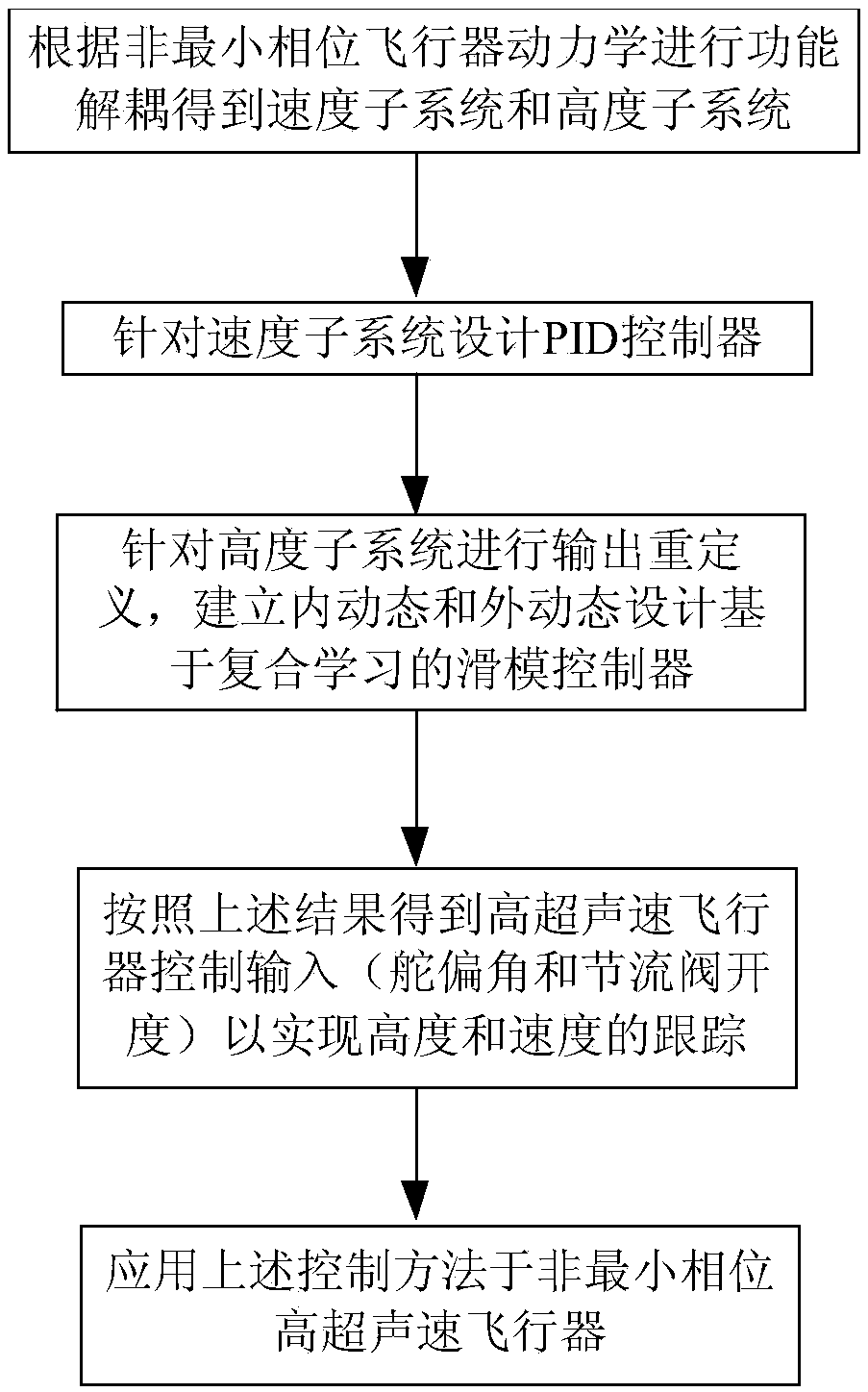
[0135] refer to figure 1 , a compound learning sliding mode control method for a non-minimum phase vehicle of the present invention is applied to a hypersonic vehicle, and is realized by the following steps:

[0136] (a) Establish a non-minimum phase hypersonic vehicle longitudinal channel dynamics model:

[0137]

[0138]

[0139]

[0140]

[0141]

[0142] Among them, V represents velocity, γ represents track inclination, h represents height, α represents angle of attack, q represents pitch angle velocity, δ eIndicates rudder deflection angle, Φ indicates throttle valve opening; T, D, L and M yy represent thrust, drag, lift and pitching moment respectively; m, I yy and g denote the mass, the moment of inertia of the pitch axis, and the acceleration due to gravity, respectively.

[0143] The relevant forces, moments and parameters are defined as follows:

[0144]

[0145]

[0146]

[0147]

[0148]

[0149]

[0150]

[0151]

[0152]...


PUM


Abstract

The invention relates to a composite learning sliding mode control method for a non-minimum phase aircraft. Firstly, a longitudinal channel model of the aircraft is decomposed into a speed subsystem and a height subsystem, the height subsystem adopts sliding mode control, and the speed subsystem adopts PID control. For the height subsystem, an unstable internal dynamic condition is changed into anasymptotically stable internal dynamic condition based on an output redefinition method, the coordinate transformation of a system internal dynamic condition after the output redefinition is carriedout, and a pitch angle instruction for the design of a controller is derived; and a neural network is used for estimating the unknown non-linear dynamics of a system, a modeling error signal is designed and combined with a sliding mode surface to provide a composite learning algorithm, and the approximation performance of the neural network to the non-linear dynamics is improved. The composite learning sliding mode control method uses the output redefinition to achieve internal dynamic condition stability and estimates uncertain dynamics of the aircraft based on a composite learning neural network, and can provide a new technical approach for the control problems of the non-minimum phase aircraft.

Description

technical field [0001] The invention relates to an aircraft control method, in particular to a compound learning sliding mode control method for a non-minimum phase aircraft, belonging to the field of aircraft control. Background technique [0002] Facing the new requirements for aircraft technology in the military and civilian fields, the flight envelope of modern aircraft continues to expand. The innovative configuration design of aircraft and the complex flight environment lead to complex nonlinear and strong uncertainty in aircraft dynamics. There is a coupling between the aircraft elevator and the aerodynamic force, which causes the aircraft to exhibit non-minimum phase characteristics. The non-minimum phase characteristics make the dynamic inverse design unable to be directly applied. At present, the influence of the elevator on the lift is mostly compensated by adding canard control surfaces, so that the system becomes a minimum phase system, but the addition of canar...

Claims


Application Information

Patent Timeline
IPC IPC(8): G05D1/08G05D1/10
CPCG05D1/0808G05D1/101
Inventor 许斌王霞杨林肖勇张君蔡华
Owner NORTHWESTERN POLYTECHNICAL UNIV
Learn More