Method and system for determining homography matrix and image conversion method and system thereof

A homography matrix and image technology, which is applied in the field of image conversion method and its system, can solve the problem of low image overlap accuracy, and achieve the effect of improving calculation accuracy, improving image overlap accuracy, and high image overlap accuracy

Active Publication Date: 2018-12-21
GUANGZHOU SHIYUAN ELECTRONICS CO LTD
View PDF4 Cites 5 Cited by
  • Summary
  • Abstract
  • Description
  • Claims
  • Application Information

AI Technical Summary

Problems solved by technology

[0005] In order to solve the above-mentioned technical problem of low image overlap accuracy of fisheye camera imaging, the embodiment of the present invention proposes a method for determining a homography matrix and its system, as well as an image conversion method and its system

Method used


Image

  • Method and system for determining homography matrix and image conversion method and system thereof
  • Method and system for determining homography matrix and image conversion method and system thereof
  • Method and system for determining homography matrix and image conversion method and system thereof

Examples


Embodiment 1

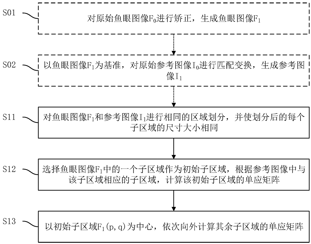
[0051] Embodiment 1 of the present invention proposes a method for determining the homography matrix, such as figure 1 As shown, the method includes the following steps:

[0052] Step S11, image area division: for fisheye image F 1 and the reference image I 1 Carry out the same area division, and make the divided fisheye image F 1 The subregion in is compared with the reference image I 1 The corresponding sub-regions in are of the same size, where the fisheye image F 1 Image from fisheye camera, reference image I 1 The fisheye image F is derived from the image formed by a common camera with a flat lens. 1 and the reference image I 1 The imaged content is the same, and the fisheye image F 1 and the reference image I 1 are the same size.

[0053] Suppose the fisheye image F 1 and the reference image I 1 Divided into m rows and n columns respectively, then each image has m*n sub-regions of the same size calculated by row and column, m and n are both natural numbers gre...

Embodiment 2

[0096] Embodiment 2 of the present invention also proposes an image conversion method, such as Figure 4 As shown, the method includes the following steps:

[0097] Step S41, determine the homography matrix: determine the fisheye image F 1 The homography matrix of each subregion in ;

[0098] The method for determining the homography matrix in step S41 is the same as the method for determining the homography matrix described in Embodiment 1, and will not be repeated here.

[0099] Step S42, sub-region image transformation: according to the homography matrix of each sub-region, the fisheye image F 1 Transform to get the transformed image F 4 , in the transformed image F 4 The area corresponding to the sub-area is intercepted, and the sub-area is transformed as the sub-area. In order to avoid that the image content at the boundary cannot be smoothly connected when each intercepted area is spliced, preferably, the intercepted area is larger than the size of the sub-area, so ...

Embodiment 3

[0120] Embodiment 3 of the present invention also proposes an image conversion system. The difference between the image conversion system proposed in Embodiment 3 and the image conversion system proposed in Embodiment 2 is that the image conversion system in Embodiment 3 may not include a determination unit The system of the homography matrix, the image conversion system in embodiment 2 includes the system of determining the homography matrix.

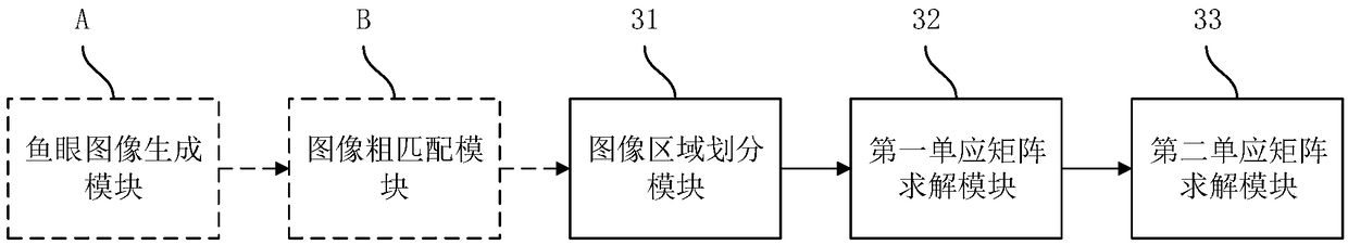
[0121] The image conversion system proposed in Embodiment 3 of the present invention includes a sub-region image conversion module and a sub-region boundary fusion module.

[0122] The sub-area image transformation module is used to determine the homography matrix of each sub-area according to the method for determining the homography matrix respectively, for the fisheye image F 1 Transform to get the transformed image F 4 , in the transformed image F 4 The area corresponding to the sub-area is intercepted, and the sub-area is transf...


PUM


Abstract

The invention relates to a method and a system for determining a homography matrix and an image conversion method and a system thereof. The method for determining the homography matrix comprises the following steps: dividing the fisheye image and the reference image into the same regions, and making the size of the sub-regions in the divided fisheye image and the corresponding sub-regions in the reference image be the same, and the size of the fisheye image and the reference image be the same; Selecting a sub-region in the fisheye image as an initial sub-region, calculating a homography matrixof the initial sub-region according to the sub-region corresponding to the sub-region in the reference image; The homography matrices of the other subregions are calculated from the center of the initial subregion. The embodiment of the invention adopts the mode of dividing regions and each sub-region corresponds to a homography matrix respectively, which has high image coincidence accuracy, andavoids the problem that in the prior art, the whole fish-eye image adopts only one homography matrix, resulting in low image coincidence accuracy of the fish-eye camera.

Description

technical field [0001] The invention belongs to the technical field of computer vision, and in particular relates to a method for determining a homography matrix and a system thereof, an image conversion method and a system thereof. Background technique [0002] The lens used in the fisheye camera is a lens with a focal length of 16mm or less and an angle of view close to or equal to 180°. Eye, so this type of camera is called a fisheye camera, and the lens used is called a fisheye lens. Fisheye lens is a special kind of ultra-wide-angle lens. Its angle of view strives to reach or exceed the range that human eyes can see. Therefore, the picture effect produced by fisheye lens exceeds what people see in real life. The scope of the regular fixed form causes a big difference between the fisheye lens and the real world scene in people's eyes. However, the picture effect produced by the flat lens used by ordinary cameras is almost close to the real world scene in people's eyes....

Claims


Application Information

Patent Timeline
Patent Type & Authority Applications(China)
IPC IPC(8): G06T3/00G06T3/40G06K9/62
CPCG06T3/0012G06T3/4038G06T7/80G06T5/006G06F18/22
Inventor 贺永刚
Owner GUANGZHOU SHIYUAN ELECTRONICS CO LTD
Why Eureka
Try Eureka