
A vibration damping ring for electric power

A vibration-absorbing ring and electric power technology, applied in the direction of transformer/inductor noise damping, etc., can solve the problems of restricting the applicability of the device, inconvenient adjustment of angle, inconvenient installation, etc., and achieve the effect of improving performance

Active Publication Date: 2020-11-24
YANGHZOU XINBAOLI METAL PRODS
View PDF10 Cites 0 Cited by
  • Summary
  • Abstract
  • Description
  • Claims
  • Application Information

AI Technical Summary

Problems solved by technology

[0002] During the use of electric power facilities, a large number of electric fittings are needed. With the help of electric fittings, the operation of electric facilities can be made more stable, and the transmission lines can be fixed more firmly. Among many electric fittings, vibration damping rings are used more , The anti-vibration ring can reduce the vibration of the electromagnet when it is in use, which can ensure the use effect of the electromagnet and ensure the stable operation of the electromagnet. The anti-vibration ring can also reduce the noise of the electromagnet and eliminate the noise around the electromagnet pollution, to ensure the stable and normal operation of the electromagnet and to ensure the overall safe operation of the transformer. At present, when installing and using the vibration damping ring on the market, it is inconvenient to install, time-consuming and laborious, and it is not easy to adjust the angle, which limits the applicability of the device.

Method used


Image

  • A vibration damping ring for electric power
  • A vibration damping ring for electric power

Examples


Embodiment Construction

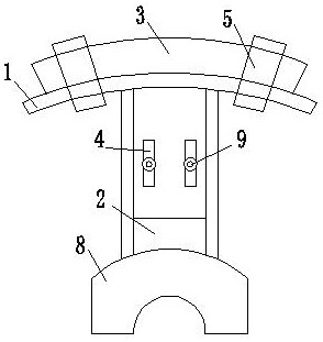
[0015] A vibration damping ring for electric power, comprising an arc-shaped connecting plate 1, a connecting plate 2, an arc-shaped fixing plate 3 and a through hole 4;

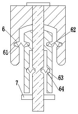
[0016] The arc-shaped connecting plate 1 and the arc-shaped fixing plate 3 are coaxially arranged, and the arc-shaped connecting plate 1 is coaxially located inside the arc-shaped fixing plate 3 and connected by a fastener 5. The arc-shaped connecting plate 1 There is a gap between the outer side and the inner side of the arc-shaped fixing plate 3, and a holding device 6 is provided at the gap to keep the arc-shaped fixing plate 3 and the arc-shaped connecting plate 1 coaxially arranged;

[0017] The holding device 6 includes: an outer blind hole 61 arranged at the corresponding position of the arc-shaped connecting plate 1 and the arc-shaped fixing plate 3, and the two ends of the outer spring 62 are arranged to interfere in the outer blind hole 61, and the arc-shaped Corresponding inner blind holes 63 are ...


PUM


Abstract

The invention relates to a vibration absorbing ring for electric power. An arc-shaped connecting plate and an arc-shaped fixing plate are coaxially arranged, that arc-shaped connecting plate is coaxially arranged on the inner side of the arc-shaped fixing plate and is connected through fasteners, there is a gap between the outer side of the arc-shaped connecting plate and the inner side of the arc-shaped fixing plate, and a holding device for keeping the arc-shaped fixing plate and the arc-shaped connecting plate to be coaxially arranged is arranged at the gap; The holding device comprises anouter blind hole arranged at a corresponding position of an arc-shaped connecting plate and an arc-shaped fixing plate, wherein two ends of the outer spring are arranged in the outer blind hole, corresponding inner blind holes are arranged on the inner side of the arc-shaped connecting plate and the fastener, and two ends of the inner spring are arranged in the inner blind hole. The inner spring and the out spring are arranged, and the inner spring and the out spring are symmetrically arranged, when the arc-shaped connecting plate and the arc-shaped fixing plate are moved due to vibration or other factors, the arc-shaped connecting plate and the arc-shaped fixing plate are returned under the restraint of the inner spring and the outer spring, and the service performance of the vibration absorbing ring is improved.

Description

technical field [0001] The invention relates to the technical field of vibration-absorbing rings, in particular to a vibration-absorbing ring for electric power. Background technique [0002] During the use of electric power facilities, a large number of electric fittings are needed. With the help of electric fittings, the operation of electric facilities can be made more stable, and the transmission lines can be fixed more firmly. Among many electric fittings, vibration damping rings are used more , The anti-vibration ring can reduce the vibration of the electromagnet when it is in use, which can ensure the use effect of the electromagnet and ensure the stable operation of the electromagnet. The anti-vibration ring can also reduce the noise of the electromagnet and eliminate the noise around the electromagnet pollution, to ensure the stable and normal operation of the electromagnet and to ensure the overall safe operation of the transformer. At present, when installing and ...

Claims


Application Information

Patent Timeline
Patent Type & Authority Patents(China)
IPC IPC(8): H01F27/33
CPCH01F27/33
Inventor 于万坤于晖
Owner YANGHZOU XINBAOLI METAL PRODS
Learn More