Eureka AIR delivers breakthrough ideas for toughest innovation challenges, trusted by R&D personnel around the world.

A Method for Reducing Discharge Breakdown Voltage in Liquid Medium

A technology of discharge breakdown and liquid medium, which is applied in the field of plasma, can solve the problems of unfavorable discharge device regulation, large discharge current, and no degree of freedom, so as to avoid discharge runaway and electrode ablation, reduce breakdown voltage, and prolong The effect of service life

Inactive Publication Date: 2020-06-30
HUAZHONG UNIV OF SCI & TECH
View PDF5 Cites 0 Cited by
  • Summary
  • Abstract
  • Description
  • Claims
  • Application Information

AI Technical Summary

Problems solved by technology

If a high enough voltage is applied to the discharge gap, although the discharge can be easily generated, there are many negative problems, including higher voltage levels that increase the size and cost of the power supply, and at the same time, if the voltage cannot be returned in time after breakdown , the stable discharge current is relatively large. On the one hand, this will cause electrode ablation and affect the life and safety of the discharge device. The working conditions are adjusted, and if the output voltage of the power supply is not high enough, the discharge cannot be generated at all.
[0003] At present, in the process of generating discharge in a liquid medium, the electrodes are clamped and fixed, and there is no degree of freedom. When applying a voltage to the two electrodes, only when the applied voltage reaches a high enough level (such as deionized water, usually when the two electrodes are in the 1 mm, the breakdown voltage is as high as 25KV or more), and the liquid medium between the electrodes can be broken down. Therefore, the requirements for the experimental equipment are extremely high, and it is difficult to implement

Method used


Image

  • A Method for Reducing Discharge Breakdown Voltage in Liquid Medium

Examples


Embodiment Construction

[0016] In order to make the object, technical solution and advantages of the present invention clearer, the present invention will be further described in detail below in conjunction with the accompanying drawings and embodiments. It should be understood that the specific embodiments described here are only used to explain the present invention, not to limit the present invention. In addition, the technical features involved in the various embodiments of the present invention described below can be combined with each other as long as they do not constitute a conflict with each other.

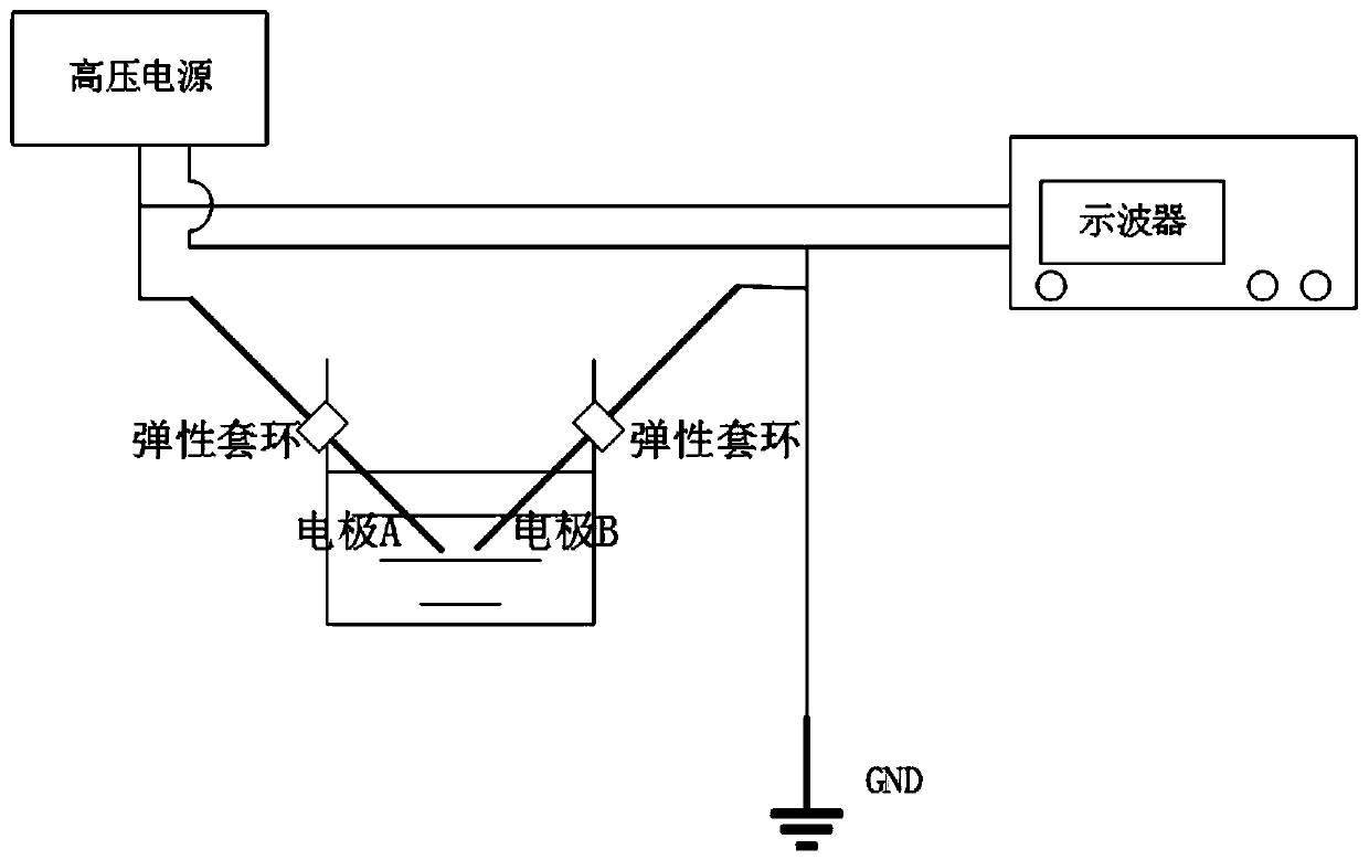
[0017] According to a preferred embodiment of the present invention, a device for discharging in a liquid medium is set up, figure 1 It is a structural schematic diagram of discharge in a medium liquid medium constructed according to a preferred embodiment of the present invention. The device includes the following structures: a high-voltage power supply, a movable electrode capable of withstand...


PUM


Abstract

The invention belongs to the technical field of the plasma discharging in the liquid medium, and discloses a method for reducing discharging breakdown voltage in liquid medium. The method comprises the following steps: S1, oppositely placing two electrodes in discharging liquid, setting initial distance between two electrodes, and then clamping two electrodes, thereby enabling at least one electrode to possess the degree of freedom of moving around the own clamping point; S2, applying high voltage between two electrodes, wherein two electrodes are mutually attracted so that bottom ends of twoelectrodes gradually close to each other, thereby shortening the distance between the two electrodes and reducing the breakdown voltage between two electrodes; and S3, gradually increasing the appliedhigh voltage until the discharging occurs between two electrodes, wherein the discharging voltage breaks down the discharging liquid between two electrodes, two electrodes are recovered to the initial distance after the discharging lighting until the breakdown process is accomplished. Through the method disclosed by the invention, the breakdown voltage in the liquid medium is reduced, the electrode ablation is avoided, the energy utilization efficiency is improved, and the discharging difficulty in the water is reduced.

Description

technical field [0001] The invention belongs to the technical field of plasma discharge in a liquid medium, and more particularly relates to a method for reducing a discharge breakdown voltage in a liquid medium. Background technique [0002] In recent years, the research and application of discharge plasma in liquid has received extensive attention at home and abroad. Discharge in liquid is of great significance in hydrogen production from ethanol reforming, sewage treatment, and sterilization. In the current research on the application of liquid phase discharge, no matter whether the electrodes of the device used are needle-plate, needle-needle, or plate-plate, the distance between the electrodes is constant. The characteristic of discharge in water is that the breakdown voltage is very high, and once the discharge is ignited, the voltage to maintain the discharge is relatively low. If a high enough voltage is applied to the discharge gap, although the discharge can be ea...

Claims


Application Information

Patent Timeline
Patent Type & Authority Patents(China)
IPC IPC(8): H05H1/46
CPCH05H1/46
Inventor 鲜于斌李宜阳
Owner HUAZHONG UNIV OF SCI & TECH
Why Eureka
Eureka Blog
Learn More