Waveguides with extended field of view

A technology of optical waveguide and light wave, applied in the field of waveguide with extended field of view

Active Publication Date: 2018-12-21
MICROSOFT TECH LICENSING LLC
View PDF6 Cites 14 Cited by
  • Summary
  • Abstract
  • Description
  • Claims
  • Application Information

AI Technical Summary

Problems solved by technology

Since this is still a nascent technology, there are some challenges with using waves to display images of virtual objects to the user

Method used


Image

  • Waveguides with extended field of view
  • Waveguides with extended field of view
  • Waveguides with extended field of view

Examples


Embodiment Construction

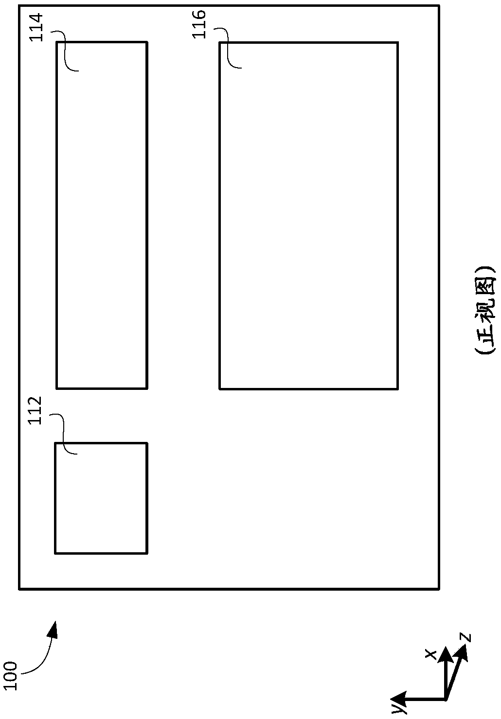
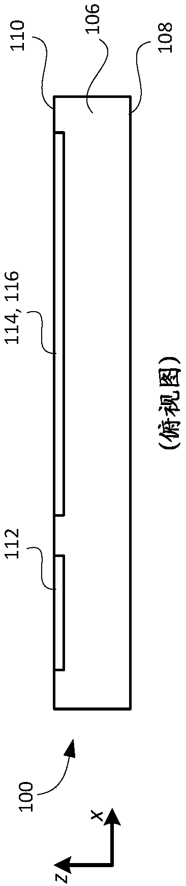
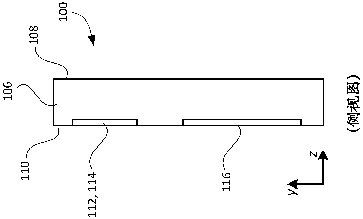
[0012] Certain embodiments of the present technology can be used to increase (also referred to as expanding) the field of view (FOV) that can be supported by an optical waveguide that includes one or more intermediate components for performing pupil expansion, where the intermediate(s) Components typically limit how large a FOV can be supported by such an optical waveguide. Before providing details of such embodiments, Figure 1A , 1B and 1C are first used to describe exemplary optical waveguides and their components, as well as their limitations. In the following description, the same numerals or reference signs will be used to refer to the same parts or elements throughout. Additionally, the first digit of each reference number identifies the figure in which the reference number first appears.

[0013] Figure 1A , 1B and 1C are front, top and side views, respectively, of an exemplary lightguide 100 that can be used to replicate an image associated with an input pupil to ...


PUM


Abstract

An input-coupler of an optical waveguide couples light corresponding to the image and having a corresponding FOV into the optical waveguide, and the input-coupler splits the FOV of the image coupled into the optical waveguide into first and second portions by diffracting a portion of the light corresponding to the image in a first direction toward a first intermediate-component, and diffracting aportion of the light corresponding to the image in a second direction toward a second intermediate-component. An output-coupler of the waveguide combines the light corresponding to the first and second portions of the FOV, and couples the light corresponding to the combined first and second portions of the FOV out of the optical waveguide so that the light corresponding to the image and the combined first and second portions of the FOV is output from the optical waveguide. The intermediate-components and the output-coupler also provide for pupil expansion.

Description

Background technique [0001] Various types of computing, entertainment, and / or mobile devices can be implemented with transparent or translucent displays through which a user of the device can view the surrounding environment. Such devices, which may be referred to as see-through, mixed reality display device systems, or augmented reality (AR) systems, enable users to see their surroundings through the device's transparent or translucent display and also see virtual objects (e.g., text, graphics, , video, etc.), these virtual objects are generated for display to appear to be part of and / or overlaid on the surrounding environment. These devices, which may be implemented as but not limited to head-mounted display (HMD) glasses or other wearable display devices, typically utilize optical waveguides to replicate images, such as those produced by a display engine, into an augmented reality environment. The user of the device may perceive the images as The location of the virtual im...

Claims


Application Information

Patent Timeline
Patent Type & Authority Applications(China)
IPC IPC(8): G02B27/00G02B27/01
CPCG02B2027/0174G02B2027/0123H04N13/332H04N13/344G02B27/0081G02B27/0172G02F1/292G02F1/295G02B30/35G02B5/18G02B5/1814G02B5/1819G02B6/0026G02B6/005G02B27/4205G02B27/44G02B2005/1804G02B2027/0125G02B2027/013
Inventor T·瓦留斯J·特沃
Owner MICROSOFT TECH LICENSING LLC
Why Eureka
Try Eureka