Eyepiece assembly using plastic aspheric element

a technology of aspheric elements and eyepieces, applied in the field of eyepiece lens assemblies, can solve the problem that no specific optical assembly has been established

Inactive Publication Date: 2001-08-28
UNITED STATES OF AMERICA THE AS REPRESENTED BY THE SEC OF THE ARMY
View PDF3 Cites 8 Cited by
  • Summary
  • Abstract
  • Description
  • Claims
  • Application Information

AI Technical Summary

Problems solved by technology

While the prior art has reported using optical eyepiece assemblies, none have established a basis for

Method used


Image

  • Eyepiece assembly using plastic aspheric element
  • Eyepiece assembly using plastic aspheric element
  • Eyepiece assembly using plastic aspheric element

Examples


Embodiment Construction

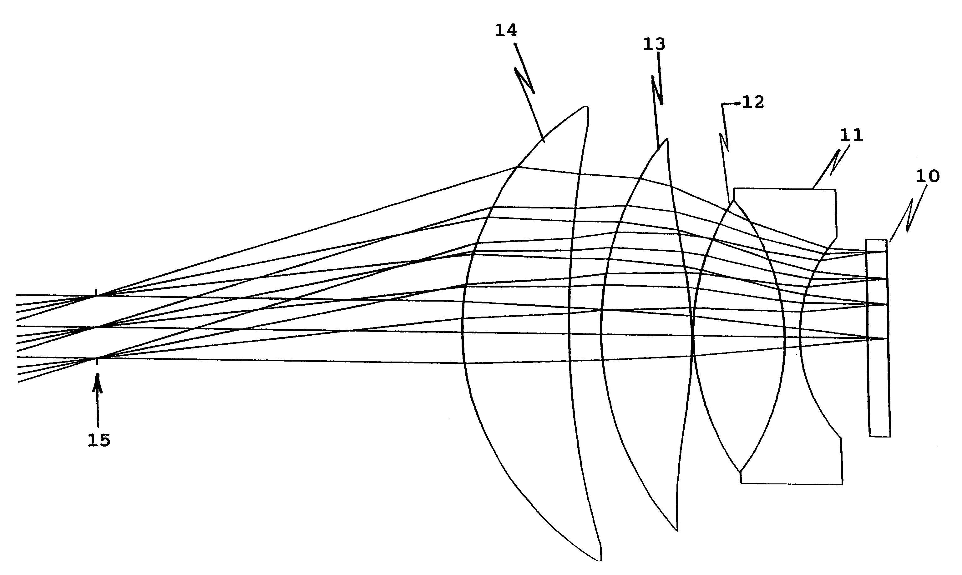
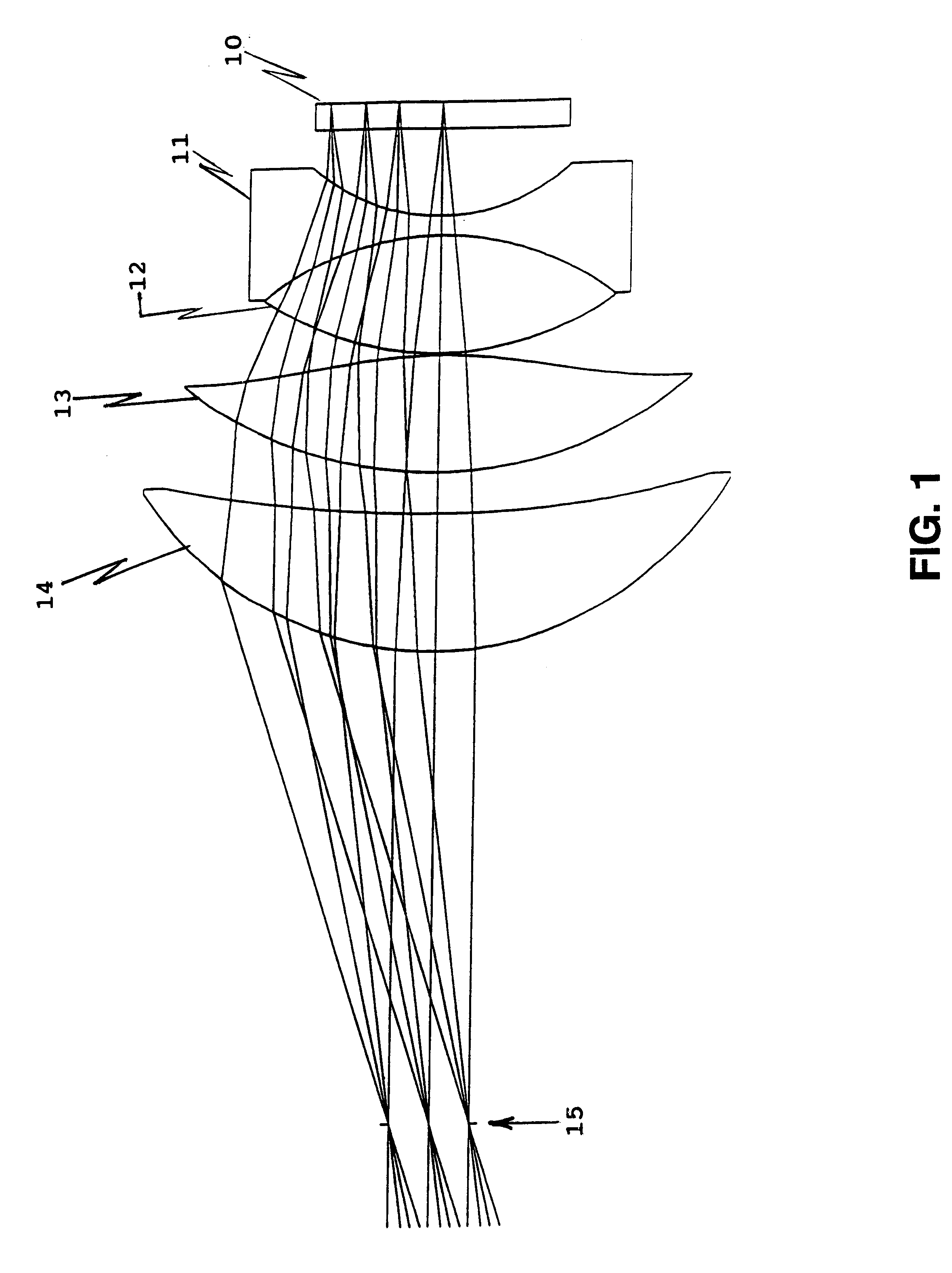
Referring now to the drawings, and more particularly to FIG. 1, there is shown an optics layout of superimposed raytraces for the optical assembly of the present invention. Light enters the optical assembly through lens element 10 which functions to collect incoming light. Light from lens element 10 proceeds into lens elements 11 and 12 that together are a glass spherical cemented doublet. Lens elements 11 and 12 provide flatness and color correction. Lens element 13 then receives light from the glass spherical cemented doublet. Lens element 13 is a plastic singlet with one aspheric surface that allows for simultaneous control of field flatness, astigmatism, and distortion. Light is then received by lens element 14, a glass spherical singlet, which provides final collimation for convergence at focal plane 15.

Table 1 details a lens prescription for the eyepiece lens assembly. A positive radius shown in the table indicates the center of curvature is to the right and a negative radius ...


PUM


Abstract

An eyepiece lens assembly including a collecting lens, glass spherical cemented doublet, a plastic singlet, and a glass spherical singlet. The assembly provides over 30 degrees extended field of view, a greater than 30 mm eye relief, under 5% distortion, a substantially telecentric focal plane, and weighing under 6 ounces.

Description

1. Field of the InventionThe present invention generally relates to eyepiece lens assemblies and more specifically, to an eyepiece lens assembly using a plastic aspheric element.2. Description of Prior ArtIt is often required that the eyepiece of a rifle scope provide an extended eye relief distance beyond 30 mm in order to prevent the event of rifle firing "kickback", forcing the scope backwards, and injuring the user's eye. In addition, for rifle scopes with modern integrated displays and reticules, it is also desirable to provide an oversized exit pupil (over 10 degrees) to accommodate eye wander and make it easier to view the display. In many cases, the modern eyepiece display assemblies may include display sources such as Cathode Ray Tubes (CRT's) or Flat Panels (such as Liquid Crystal Displays), in which case it may be also required that a lightweight eyepiece (under 6 ounces) is used. The eyepiece must also provide its own distortion correction independent of any objective op...

Claims


Application Information

Patent Timeline
IPC IPC(8): G02B25/00
CPCG02B25/001
Inventor HALL, JOHN M.
Owner UNITED STATES OF AMERICA THE AS REPRESENTED BY THE SEC OF THE ARMY
Why Eureka
Try Eureka