Personal display system with extended field of view

a display system and extended field of view technology, applied in the field of personal display systems, can solve the problems of limited field of view (fov) received by the user, tightly limited eye relief and optics diameter

Active Publication Date: 2012-07-03
ELBIT SYST LTD
View PDF10 Cites 9 Cited by
  • Summary
  • Abstract
  • Description
  • Claims
  • Application Information

AI Technical Summary

Problems solved by technology

In a typical system that establishes a conforming head wearing unit, the field of view (FOV) received by the user is limited due to both li...

Method used


Image

  • Personal display system with extended field of view
  • Personal display system with extended field of view
  • Personal display system with extended field of view

Examples


Embodiment Construction

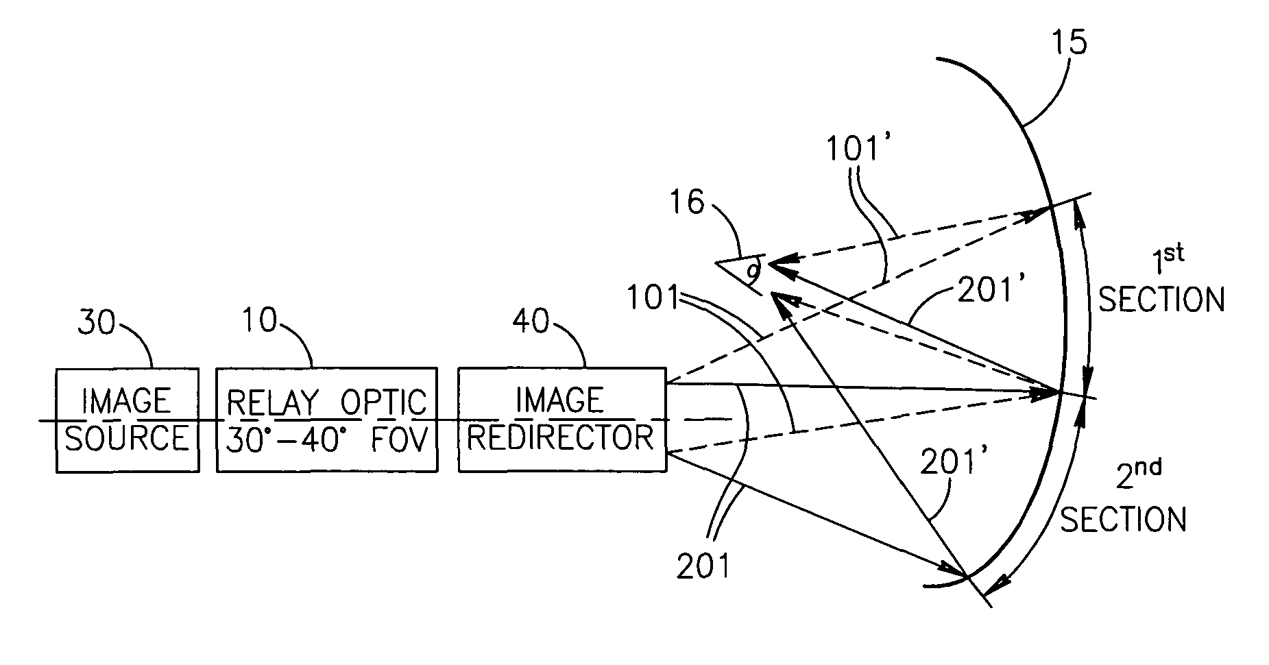
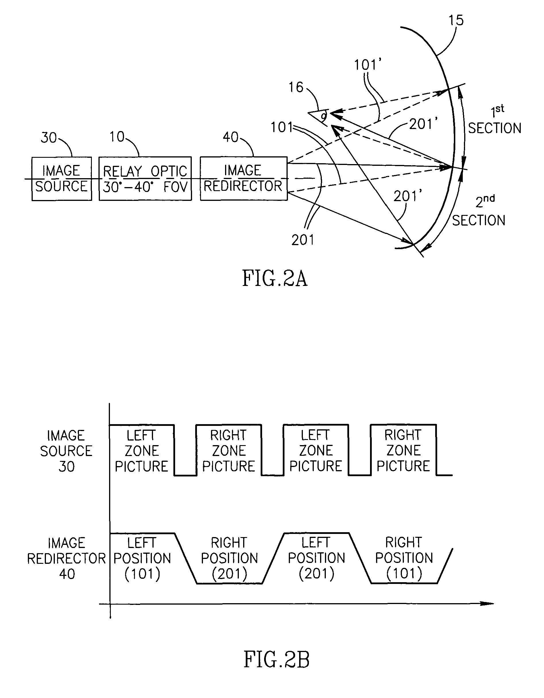
[0013]An optical system is disclosed, utilizing relay optics and visor, with increased FOV and using a lightweight relay optics. According to the current invention the image projected to the viewer 16 is composed of two or more fractions, each is displayed utilizing substantially full FOV of the relay optics (which has smaller FOV compared with the combined total FOV). The FOV for the viewer is achieved without substantially increasing the system's weight and without substantially lowering the resolution of the projected image.

[0014]FIG. 2A illustrates a preferred embodiment of the current invention according to which an image is produced by image source 30, received by relay optics 10, deviated / reflected at a high speed in more than one direction by image redirector 40, and superimposed in visor 15 in more than one location. The images, from more than one location, reflect off the visor 15 and are received by the eye of the user 16. Since the switch between the image fractions bein...


PUM


Abstract

A system and method for providing extended field of view. In one embodiment, the present invention is directed to provide extended field of view for a user of a personal display system. The system may include an image source coupled to relay optics, to redirecting unit and to reflecting unit, and may optionally be mounted in a helmet.

Description

FIELD OF INVENTION[0001]The current invention relates to personal display systems in general, and to head mounted personal display systems in more particular.BACKGROUND OF THE INVENTION[0002]It is often desirable to display off of the visor of a helmet an optical image. This is generally useful for applications such as flight borne helmets where the viewer (e.g. a pilot) desires to see pictures or symbols reflected off the visor.[0003]Reference is now made to FIG. 1A describing a typical helmet-mounted, prior art optical system involving a visor. The helmet typically comprises an image source 30 and relay optics 10. A picture is relayed from source 30, through Relay Optics 10, reflected off a visor 15 or combiner element, and into the viewer's eye 16, such as a pilot. In a typical system that establishes a conforming head wearing unit, the field of view (FOV) received by the user is limited due to both limited eye relief and limited optics diameter. Typically a reduced FOV of 30° to...

Claims


Application Information

Patent Timeline
IPC IPC(8): G03H1/02G02B27/14G02B5/30G02B27/00G02B27/01
CPCG02B27/0101G02B27/0172G02B5/30G02B2027/0154
Inventor YONA, ZVIABRAHAM, SASSONSHALOM, SHMUELARLIEVSKY, ARONHAMBURGER, ODED
Owner ELBIT SYST LTD
Why Eureka
Try Eureka