System and Method for Imbedded, High-Spatial Resolution, Fluoroscopic Tracking of Multi-Station, Contrast-Enhanced Magnetic Resonance Angiography

Active Publication Date: 2012-10-04
MAYO FOUND FOR MEDICAL EDUCATION & RES
View PDF4 Cites 7 Cited by
  • Summary
  • Abstract
  • Description
  • Claims
  • Application Information

AI Technical Summary

Benefits of technology

[0020]The present invention overcomes the aforementioned drawbacks by providing a system and method for high-resolution, fluoroscopic tracking of table motion in a multi-station, contrast-enhanced MR angiography study of the peripheral vasculature. The method combines high-speed MR imaging with interactive control of the patient table and allows the table position to track the c

Problems solved by technology

There are a wide variety of technical challenges to performing CE-MRA to yield the desired information for a particular setting.
If the central lines of k-space are acquired prior to the arrival of contrast, severe image artifacts can limit the diagnostic information in the image.
However, this timing constraint is in opposition with the need to obtain a high spatial resolution image, for example, a three-dimensional (3D) image with adequate spatial resolution.
Short TR acquisition sequences severely limit the signal-to-noise ratio (SNR) of the acquired images relative to those exams in which longer TRs are possible.
The rapid acquisitions required by first-pass CE-MRA methods thus impose an upper limit on either spatial or temporal resolution.
Imaging of the peripheral vasculature, defined roughly as those vessels contained within the region extending from the pelvis to the feet, poses additional technical challenges.
One method for matching image acquisition to peak arterial contrast, but limited to the first station, is fluoroscopic triggering.
However, at the time of triggering the real-time presentation of contrast advance ceases, and the observer has no knowledge about the subsequent speed of advance of the contrast bolus

Method used


Image

  • System and Method for Imbedded, High-Spatial Resolution, Fluoroscopic Tracking of Multi-Station, Contrast-Enhanced Magnetic Resonance Angiography
  • System and Method for Imbedded, High-Spatial Resolution, Fluoroscopic Tracking of Multi-Station, Contrast-Enhanced Magnetic Resonance Angiography
  • System and Method for Imbedded, High-Spatial Resolution, Fluoroscopic Tracking of Multi-Station, Contrast-Enhanced Magnetic Resonance Angiography

Examples


Embodiment Construction

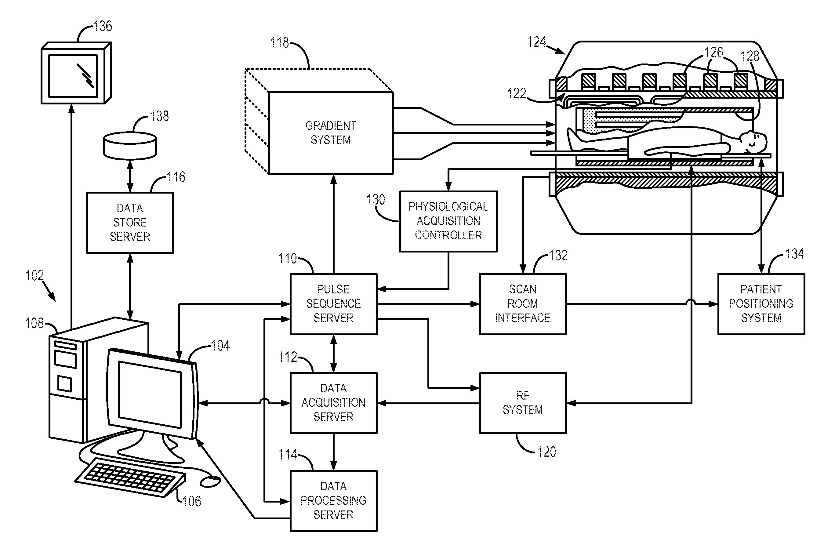
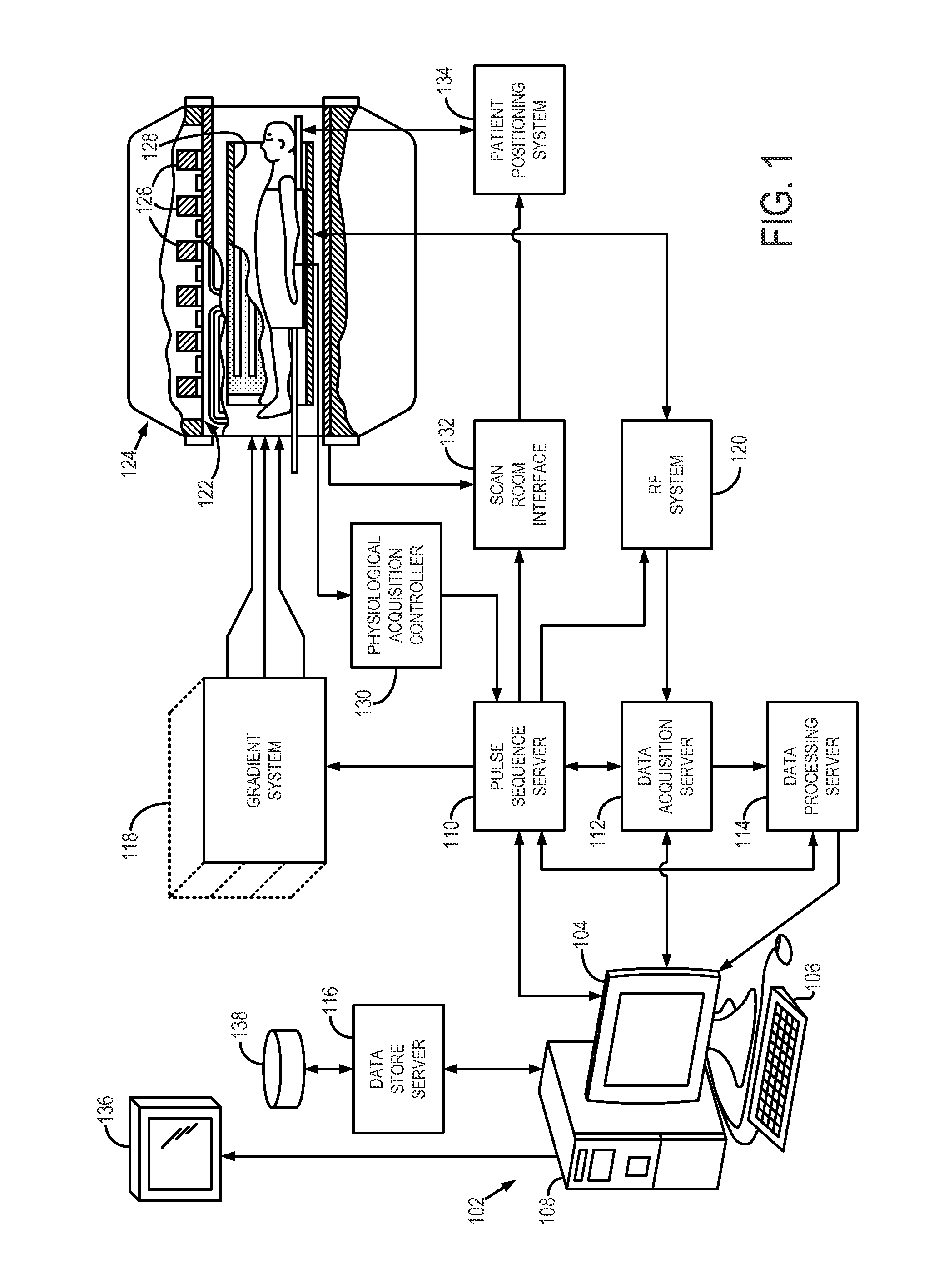
[0030]Referring particularly to FIG. 1, an exemplary magnetic resonance imaging (“MRI”) system 100 is shown. The MRI system 100 includes a workstation 102 having a display 104 and a keyboard 106. The workstation 102 includes a processor 108, such as a commercially available programmable machine running a commercially available operating system. The workstation 102 provides the operator interface that enables scan prescriptions to be entered into the MRI system 100. The workstation 102 is coupled to four servers: a pulse sequence server 110; a data acquisition server 112; a data processing server 114, and a data store server 116. The workstation 102 and each server 110, 112, 114 and 116 are connected to communicate with each other.

[0031]The pulse sequence server 110 functions in response to instructions downloaded from the workstation 102 to operate a gradient system 118 and a radiofrequency (“RF”) system 120. Gradient waveforms necessary to perform the prescribed scan are produced a...


PUM


Abstract

A method of producing a series of vasculature images over an extended field of view (FOV) larger than an FOV of an MRI system includes acquiring initial time-resolved image data from the vasculature and, during the acquiring process, reconstructing, in substantially real-time, a series of three-dimensional (3D) tracking images of the initial portion of the vasculature illustrating a current position of a contrast bolus in the vasculature as the contrast bolus passes through the initial portion of the vasculature. Based on a current position of the contrast bolus, the subject is moved to a subsequent imaging station to acquire subsequent time-resolved image data and reconstruct subsequent 3D tracking images of subsequent portions of the vasculature. This process is repeated and then an image is assembled that extends over the extended FOV using the initial time-resolved image data and the subsequent time-resolved image data.

Description

CROSS-REFERENCE[0001]This application is based on, claims the benefit of, and incorporates herein in its entirety by reference, U.S. Provisional Application Ser. No. 61 / 470,550, entitled “SYSTEM AND METHOD FOR IMBEDDED, HIGH-SPATIAL RESOLUTION, FLUOROSCOPIC TRACKING OF MULTI-STATION, CONTRAST-ENHANCED MAGNETIC RESONANCE ANGIOGRAPHY,” and filed Apr. 1, 2011.STATEMENT REGARDING FEDERALLY SPONSORED RESEARCH[0002]This invention was made with government support under HL070620 awarded by the National Institutes of Health. The government has certain rights in this invention.BACKGROUND OF THE INVENTION[0003]The present invention relates generally to magnetic resonance imaging (“MRI”) systems and methods and, more particularly, the invention relates to systems and methods for performing contrast-enhanced magnetic resonance angiography (CE-MRA) of a subject using high-spatial resolution, fluoroscopic images imbedded within the CE-MRA study as a trigger for coordinating the CE-MRA study with d...

Claims


Application Information

Patent Timeline
IPC IPC(8): A61B5/055A61B6/00
CPCA61B5/055G01R33/5619A61B5/7285A61B5/004G01R33/5611G01R33/5635G01R33/56383G01R33/4824
Inventor RIEDERER, STEPHEN J.JOHNSON, CASEY P.
Owner MAYO FOUND FOR MEDICAL EDUCATION & RES
Why Eureka
Try Eureka