Check patentability & draft patents in minutes with Patsnap Eureka AI!

Substrate support, lithographic apparatus and loading method

A technology for substrate supports and substrates, which is applied in microlithography exposure equipment, photomechanical equipment, exposure devices for photolithography, etc., and can solve problems affecting the overlay performance of lithography equipment, etc.

Active Publication Date: 2018-12-21
ASML NETHERLANDS BV
View PDF4 Cites 1 Cited by
  • Summary
  • Abstract
  • Description
  • Claims
  • Application Information

AI Technical Summary

Problems solved by technology

Since the position and / or shape may differ in different shots on the same substrate, internal stresses may adversely affect the overlay performance of the lithographic apparatus

Method used


Image

  • Substrate support, lithographic apparatus and loading method
  • Substrate support, lithographic apparatus and loading method
  • Substrate support, lithographic apparatus and loading method

Examples


Embodiment Construction

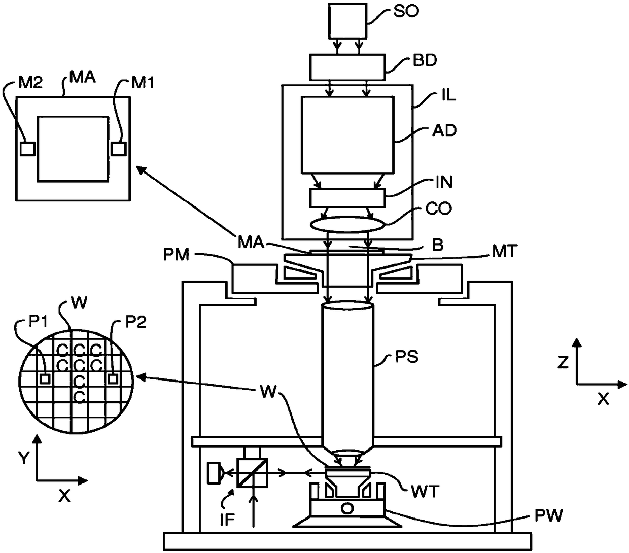
[0038] figure 1 A lithographic apparatus according to an embodiment of the invention is schematically depicted. The apparatus comprises an illumination system (illuminator) IL configured to condition a radiation beam B (e.g., UV radiation or any other suitable radiation), configured to support a patterning device (e.g., a mask) MA and connected to a The mask support structure (eg mask table) MT of the first positioning apparatus PM is for accurately positioning the patterning device according to certain parameters. The apparatus also includes a substrate support ( For example, wafer table) WT or "substrate table". The apparatus further comprises a projection system (e.g., a refractive projection lens) configured to project a pattern imparted to the radiation beam B onto a target portion C (e.g., comprising one or more dies) of the substrate W by the patterning device MA. system) PS.

[0039] The illumination system IL may include various types of optical components, such ...


PUM


Abstract

The invention relates to a substrate support (WT) for supporting a substrate (W). The substrate support comprises the main body (MB), a clamping device (VC; VSO) and a dither device (DD). The main body comprises the support surface (S) for supporting the substrate (W). The clamping device is arranged to provide the clamping force to clamp the substrate on the support surface. The dither device isconfigured to dither the clamping force. The dither device may be configured to dither the clamping force while the substrate W is being loaded onto the support surface.

Description

[0001] Cross References to Related Applications [0002] This application claims priority from EP application 16166176.4 filed on 20 April 2016, which is hereby incorporated by reference in its entirety. technical field [0003] The invention relates to a substrate support, a lithographic apparatus and a loading method. Background technique [0004] A lithographic apparatus is a machine that applies a desired pattern to a substrate, usually a target portion of the substrate. For example, lithographic equipment can be used to fabricate integrated circuits (ICs). In this case, a patterning device (alternatively called a mask or reticle) may be used to generate the circuit pattern to be formed on the individual layers of the IC. The pattern can be transferred to a target portion (eg, a portion including one or several dies) on a substrate (eg, a silicon wafer). The transfer of the pattern is usually via imaging onto a layer of radiation-sensitive material (resist) provided ...

Claims


Application Information

Patent Timeline
Patent Type & Authority Applications(China)
IPC IPC(8): G03F7/20
CPCG03F7/70716G03F7/707H01L21/68714G03F7/70691G03F7/70733G03F7/70708
Inventor J·奥努勒A·F·J·德格罗特W·西门斯D·F·弗勒斯
Owner ASML NETHERLANDS BV
Features
  • R&D
  • Intellectual Property
  • Life Sciences
  • Materials
  • Tech Scout
  • Unparalleled Data Quality
  • Higher Quality Content
  • 60% Fewer Hallucinations
Learn More