Plug contact

A technology of contact parts and contact holes, which is applied in the directions of contact parts, connection, fixed connection, etc., can solve the problems of cost and separation, difficulty in realization, and inability to connect.

Active Publication Date: 2018-12-21
PHOENIX CONTACT GMBH & CO KG
View PDF8 Cites 1 Cited by
  • Summary
  • Abstract
  • Description
  • Claims
  • Application Information

AI Technical Summary

Problems solved by technology

The disadvantage of soldering and press-fitting is that the two joining techniques are irreversible, so that a once-established connection cannot or can only be separated again with great effort
Subsequent detachment of the connection is however not possible or only difficult to achieve

Method used


Image

  • Plug contact
  • Plug contact
  • Plug contact

Examples


Embodiment Construction

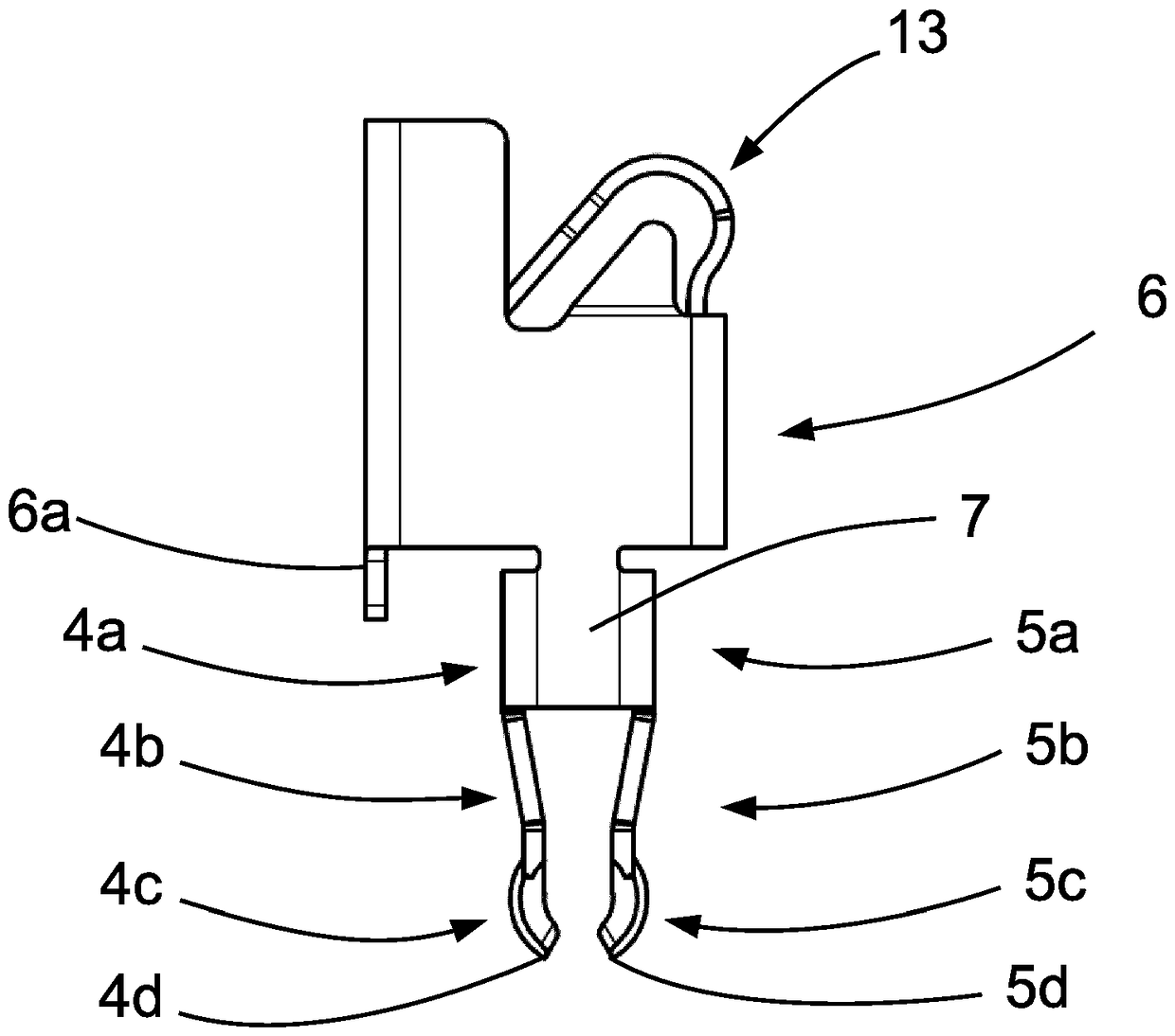
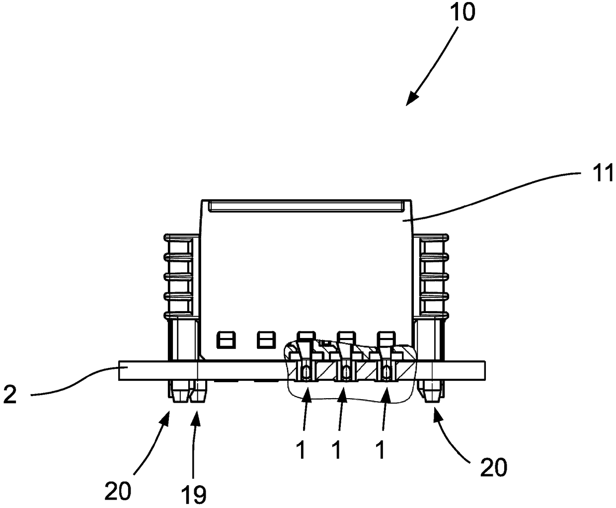
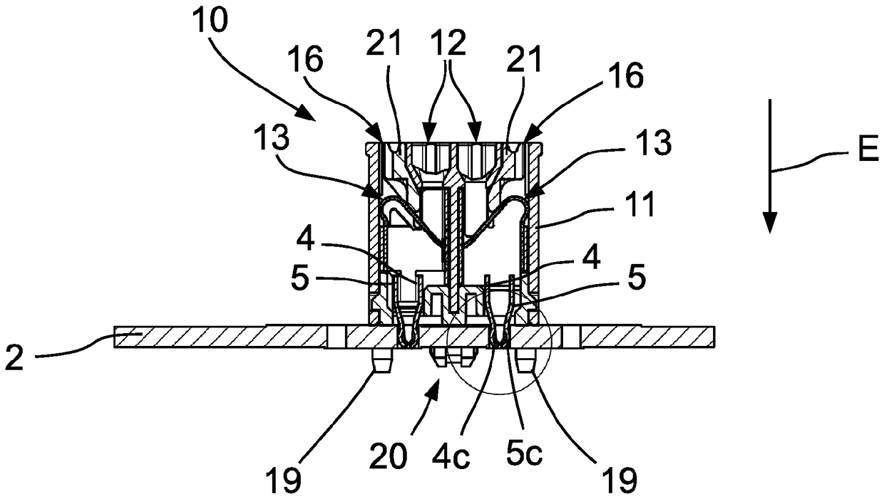
[0034] figure 1 with 2 A preferred embodiment of a plug contact 1 for contacting a circuit board 2 is shown, for which purpose the plug contact 1 is inserted into a corresponding contact hole 3 in the circuit board 2 (see Image 6 with 7 ). The punched and bent plug-in contact 1 from a metallic flat material has two contact legs 4 , 5 that are elastic relative to each other, a contact region 6 and a connection region 7 , wherein the two contact legs 4 , 5 are connected to each other via the connection region 7 . Connected and connected to joint area 6.

[0035] The two contact legs 4 , 5 each have a first section 4 a , 5 a and a second section 4 b , 5 b , which are respectively connected to the first section 4 a , 5 a in the insertion direction E of the plug-in contact 1 . as especially from figure 1 As can be seen, the two contact legs 4 , 5 are bent from the plane of the connecting region 7 , so that the connecting region 7 and the connected first regions 4 a , 5 a of t...


PUM


Abstract

The invention relates to a plug contact (1) for electrically contacting a circuit board (2) by means of the insertion of the plug contact (1) into a contact hole (3) of the circuit board (2). The plugcontact comprises two contact legs (4, 5), which are resilient relative to each other, a connection region (6), and a connecting region (7), wherein the connecting region (7) connects the two contactlegs (4, 5) to one another and to the connection region (6) and the plug contact (1) is stamped from a flat metal material and is bent. The plug contact (1) according to the invention enables securecontacting, even in the case of a small material thickness of the flat material, in that the two contact legs (4, 5) each have a first section (4a, 5a) and a second section (4b, 5b) adjoining the first section in the insertion direction (E) of the plug contact (1), wherein the two contact legs (4, 5) are bent from the plane of the connecting region (7) such that the connecting region (7) and the first regions (4a, 5a) of the two contact legs (4, 5) adjoining the connecting region (7) together form a U-shaped contour, and that a contacting region (4c, 5c) that contacts the contact hole (3) in the inserted state is formed on each of the outer faces of the two sections (4b, 5b) of the two contact legs (4, 5), which outer faces face away from each other.

Description

technical field [0001] The invention relates to a plug contact for electrically contacting a circuit board by inserting the plug contact into a contact hole of the circuit board, having two contact legs that are elastic relative to each other, a contact area and a connection area, wherein the connection area enables The two contact legs are connected to each other and to the terminal area, and the plug-in contact is formed from a metallic flat material. [0002] Furthermore, the invention relates to an electrical connection terminal with a housing, a conductor connection element and a busbar part, wherein the conductors to be connected can be electrically conductively connected to the busbar part by means of the conductor connection element, and in which a useful Conductor lead-in openings for leading electrical conductors to be connected. Background technique [0003] Plug contacts for establishing an electrical connection between conductors, various electrical or electron...

Claims


Application Information

Patent Timeline
Patent Type & Authority Applications(China)
IPC IPC(8): H01R12/58H01R12/75H01R4/48
CPCH01R12/75H01R12/585H01R4/48365H01R13/05
Inventor A.沙夫迈斯特R.格斯克
Owner PHOENIX CONTACT GMBH & CO KG
Why Eureka
Try Eureka