Wall punching device for building

A kind of punching equipment and construction technology, applied in stone processing equipment, work accessories, manufacturing tools, etc., can solve the problems of hole drilling deviation, reduce work efficiency, arm pain, etc., achieve precise drilling position, convenient drilling, Precisely Controlled Effects

Inactive Publication Date: 2018-12-25
秦汝龙
View PDF8 Cites 0 Cited by
  • Summary
  • Abstract
  • Description
  • Claims
  • Application Information

AI Technical Summary

Problems solved by technology

[0002] When people need to install water pipes and other facilities on the wall, they generally first punch holes in the wall. , so it is difficult for people to ensure that the arm does not shake, and it is impossible to ensure that the punching equipment is at the same level. It's aesthetically pleasing, and it also reduces productivity, while people holding punches for long periods of time can cause sore arms

Method used


Image

  • Wall punching device for building
  • Wall punching device for building
  • Wall punching device for building

Examples


Embodiment 1

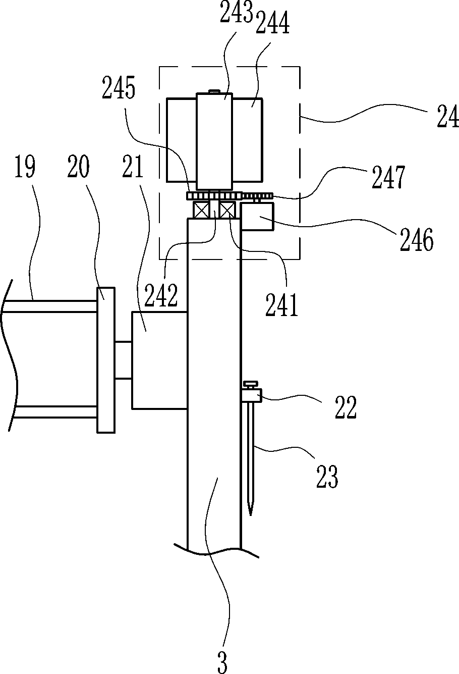
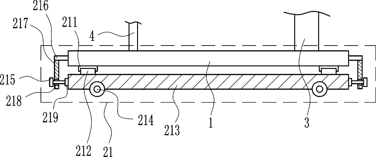
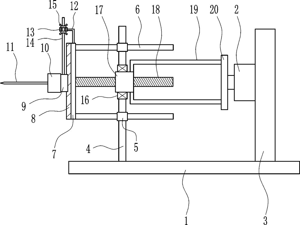
[0023] A device for punching holes in walls for construction, such as Figure 1-5 As shown, it includes a bottom plate 1, a first motor 2, a bracket 3, a mounting plate 4, a first guide sleeve 5, a guide rod 6, a first connecting plate 7, a first slide rail 8, a first slider 9, a second Motor 10, drill bit 11, L-shaped connecting rod 12, ring 13, first bolt 14, butterfly nut 15, first bearing seat 16, first nut 17, screw rod 18, L-shaped strut 19 and second connecting plate 20. There is a mounting plate 4 on the left side of the top of the bottom plate 1. The first guide sleeve 5 is provided on the upper and lower parts of the mounting plate 4. The guide rod 6 is slidably connected to the first guide sleeve 5, and the left end of the guide rod 6 is connected to the second guide sleeve. A connection plate 7, the first slide rail 8 is embedded in the middle part of the left side of the first connection plate 7, the first slide block 9 is slidably connected to the first slide rai...

Embodiment 2

[0025] A device for punching holes in walls for construction, such as Figure 1-5 As shown, it includes a bottom plate 1, a first motor 2, a bracket 3, a mounting plate 4, a first guide sleeve 5, a guide rod 6, a first connecting plate 7, a first slide rail 8, a first slider 9, a second Motor 10, drill bit 11, L-shaped connecting rod 12, ring 13, first bolt 14, butterfly nut 15, first bearing seat 16, first nut 17, screw rod 18, L-shaped strut 19 and second connecting plate 20. There is a mounting plate 4 on the left side of the top of the bottom plate 1. The first guide sleeve 5 is provided on the upper and lower parts of the mounting plate 4. The guide rod 6 is slidably connected to the first guide sleeve 5, and the left end of the guide rod 6 is connected to the second guide sleeve. A connection plate 7, the first slide rail 8 is embedded in the middle part of the left side of the first connection plate 7, the first slide block 9 is slidably connected to the first slide rai...

Embodiment 3

[0028] A device for punching holes in walls for construction, such as Figure 1-5 As shown, it includes a bottom plate 1, a first motor 2, a bracket 3, a mounting plate 4, a first guide sleeve 5, a guide rod 6, a first connecting plate 7, a first slide rail 8, a first slider 9, a second Motor 10, drill bit 11, L-shaped connecting rod 12, ring 13, first bolt 14, butterfly nut 15, first bearing seat 16, first nut 17, screw rod 18, L-shaped strut 19 and second connecting plate 20. There is a mounting plate 4 on the left side of the top of the bottom plate 1. The first guide sleeve 5 is provided on the upper and lower parts of the mounting plate 4. The guide rod 6 is slidably connected to the first guide sleeve 5, and the left end of the guide rod 6 is connected to the second guide sleeve. A connection plate 7, the first slide rail 8 is embedded in the middle part of the left side of the first connection plate 7, the first slide block 9 is slidably connected to the first slide rai...


PUM


Abstract

The invention relates to a punching device, in particular to a wall punching device for a building. The wall punching device for the building can automatically punch a wall and punched holes are located at the same level. The wall punching device for the building comprises a bottom plate, a first motor, a bracket, a mounting plate, first guiding sleeves, guiding rods, first connecting plates, a first sliding rail and the like. The mounting plate is arranged on the left side of the top of the bottom plate; the first guide sleeves are disposed on the upper portion and the lower portion of the mounting plate, and the first guide sleeves are internally and slidably connected with the guiding rods, and the first connecting plates are connected to the left ends of the guiding rods. The wall punching device controls the rotation of the first motor by people, and finally a drill bit can automatically punch the wall, since the drill bit is always at the same level, the punched holes are furtherlocated at the same level, so that the punched holes are not wasted, the beauty of the wall is nit destroyed, and people do not need to hold the punching device, so that the sore of arms of the people are not caused.

Description

technical field [0001] The invention relates to a punching device, in particular to a punching device for a building wall. Background technique [0002] When people need to install water pipes and other facilities on the wall, they generally first punch holes in the wall. , so it is difficult for people to ensure that the arm does not shake, and it is impossible to ensure that the punching equipment is at the same level. It's aesthetically pleasing, and it also reduces productivity, while people holding punches for long periods of time can cause sore arms. Contents of the invention [0003] In order to overcome the shortcomings that people need to punch holes with hand-held punching equipment, it is easy to cause pain in people's arms, and it is difficult to keep the holes punched at the same level. Holes at the same level as building wall punching equipment. [0004] A building wall punching equipment, including a base plate, a first motor, a bracket, a mounting plate,...

Claims


Application Information

Patent Timeline
Patent Type & Authority Applications(China)
IPC IPC(8): B28D1/14B28D7/00
CPCB28D1/14B28D7/00
Inventor 秦汝龙
Owner 秦汝龙
Why Eureka
Try Eureka