Toggle rod-type servo pressing machine

A servo press, toggle technology, applied in the direction of presses, punching machines, manufacturing tools, etc., can solve the problems of high manufacturing cost, small batches, hindering the level of stamping technology, etc., to achieve simple and compact structure, low cost, high pressure The effect of diverse working curves

Inactive Publication Date: 2012-10-10
SHANDONG UNIV OF SCI & TECH
View PDF0 Cites 1 Cited by
  • Summary
  • Abstract
  • Description
  • Claims
  • Application Information

AI Technical Summary

Problems solved by technology

[0002] In the field of metal forming processing, especially in sheet metal stamping, forming, and sheet stretching processes, the traditional mechanical press uses a fixed-speed motor as the power source, so that the actuator works with a fixed pressure curve, which cannot be obtained by users. According to the pressure working curve required by different processing techniques, the inherent defect of this kind of press lacks "flexibility" hinders the further improvement of stamping process level, and it is difficult to meet the requirements of modern market product diversification, fast change and small batch
In recent years, mechanical presses directly driven by servo motors have appeared, such as connecting rod presses from Amino Corporation in Japan, Komatsu HF series presses in Japan, and presses from Qiqihar Second Machine Tool Group. The press is basically the same, only the ordinary motor is replaced by a servo motor, and the speed characteristics and dynamic performance of the slider can be improved by adjusting the input of the servo motor. Since this kind of press does not use a flywheel, all the energy is provided by the servo motor during stamping. When a large-tonnage press is required, a high-power servo motor is required, but the high-power servo motor is very expensive, so the manufacturing cost of this press is very high

Method used


Image

  • Toggle rod-type servo pressing machine

Examples


Embodiment Construction

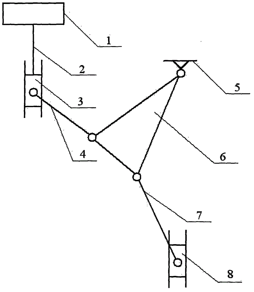
[0007] Such as figure 1 The specific embodiment of the present invention shown is a toggle-type servo press, and the press includes a servo motor 1, a ball screw 2, a slider 3, a connecting rod 4, three pairs of swing rods 6, and a frame 5. The hammer connecting rod 7 and the hammer 8, the servo motor 1 and the slider 3 are connected through the ball screw pair 2, one end of the connecting rod 4 is connected with the slider 3 through a rotating pair, and the three pairs The three nodes of the pendulum 6 are respectively connected with the connecting rod 4, the rack 5, and the hammer connecting rod 7 through the rotating pair, and the end of the hammer connecting rod 7 is connected with the punch 8 through the rotating pair, and the punch 8 is in a fixed position. within the rails.

[0008] When working, the ball screw pair 2 is used to convert the rotational motion of the servo motor 1 into a linear motion, thereby driving the slider 3 to move in the vertical direction, the c...


PUM


Abstract

The invention relates to a toggle rod-type servo pressing machine which comprises a servomotor, a ball screw, a sliding block, a connecting rod, a triangular swing stem, a machine frame, a punch hammer connecting rod and a punch hammer, wherein the servomotor and the sliding block are connected through a ball screw assembly; one end of the connecting rod and the sliding block are connected through a revolute pair; three nodes of the triangular swing stem are respectively connected with the connecting rod, the machine frame and the punch hammer connecting rod through the revolute pairs; the tail end of the punch hammer connecting rod is connected with the punch hammer through each revolute pair; and the punch hammer is positioned in a fixed guide rail. According to the matching of the servomotor and the ball screw, the punching speed and the punching position of the punch hammer can be controlled accurately; in addition, the triangular swing stem is additionally arranged, so that the pressure working curve of the punch hammer can also be diversified, and various requirements of the punching operation can be met.

Description

technical field [0001] The invention relates to non-cutting metal forming processing equipment, in particular to a servo press. Background technique [0002] In the field of metal forming processing, especially in sheet metal stamping, forming, and sheet stretching processes, the traditional mechanical press uses a fixed-speed motor as the power source, so that the actuator works with a fixed pressure curve, which cannot be obtained by users. According to the pressure working curve required by different processing techniques, the inherent defect of this kind of press lacks "flexibility" which hinders the further improvement of the stamping process level, and it is difficult to meet the requirements of modern market product diversification, rapid change, and small batches. In recent years, mechanical presses directly driven by servo motors have appeared, such as connecting rod presses from Amino Corporation in Japan, Komatsu HF series presses in Japan, and presses from Qiqiha...

Claims


Application Information

Patent Timeline
Patent Type & Authority Applications(China)
IPC IPC(8): B30B1/10
Inventor 陈修龙邓昱
Owner SHANDONG UNIV OF SCI & TECH
Why Eureka
Try Eureka