Stamping apparatus with feed device

A technology for equipment and stamping tools, which is applied in the field of stamping equipment with a supply device to achieve the effects of reducing the number of lateral positioning, increasing the output of parts, and saving tool costs

Inactive Publication Date: 2011-06-08
弗兰克・霍夫曼
View PDF2 Cites 0 Cited by
  • Summary
  • Abstract
  • Description
  • Claims
  • Application Information

AI Technical Summary

Problems solved by technology

The known device has a large structural depth, since it has to receive at least two metal plates in the direction of passage

Method used


Image

  • Stamping apparatus with feed device
  • Stamping apparatus with feed device
  • Stamping apparatus with feed device

Examples


Embodiment Construction

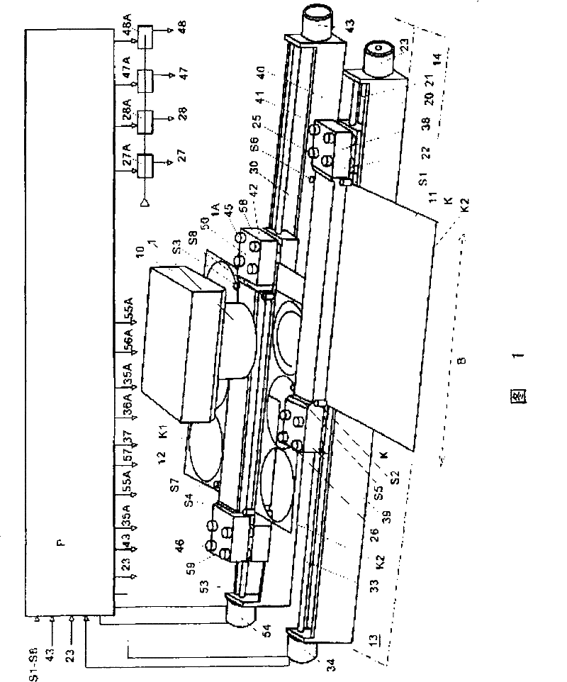
[0027] figure 1 The brackets 13 , 14 on both sides are schematically shown, on which two transverse conveyors 20 , 40 are mounted, including their positioning drive motors 23 , 43 and roller drive motors 34 , 54 . Between the supports 13 , 14 extends a schematically shown bridge 10 , on which the extrusion and stamping tool 1 is mounted, and coaxially therewith a die 1A is arranged underneath in the support. The two transverse conveyors 20 , 40 are each formed by a slide guide 21 , 41 which extend over at least the two largest sheet metal widths B .

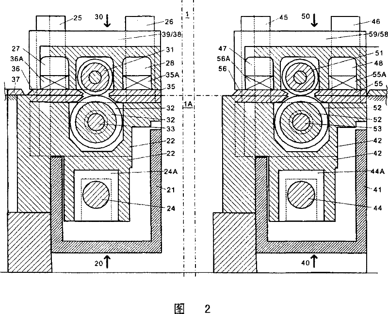
[0028] In the slide guides 21, 41, a slide 22, 42 is respectively laterally displaceably supported, which is connected to a linear drive, such as a screw drive, whose drive motor 23, 43 drives a The invisible threaded spindle extends longitudinally in the slide guide and through the slides 22, 42, in which a threaded spindle nut is mounted.

[0029] Two drive rollers are mounted one above the other in each slide 22 , 42 , wher...


PUM


Abstract

The invention describes an apparatus for stamping can lids or the like, having a bridge (10) supported on a frame and carrying stamping tools (1) actuated vertically in a continuously repeating manner, having a longitudinal conveying device (30) gradually transporting metal sheets (11, 12) under said tools (1) in each case with the latter opened, and having a transverse conveying device (20, 40) laterally displacing to a limited extent the metal sheet (11, 12) moving or moved longitudinally in each case, wherein a separately controllable transverse conveying device (20, 40) is arranged in a stationary position in each case on the feed and discharge side approximately symmetrically to the tools (1) close in front of and behind the latter, said transverse conveying device (20, 40) in each case carrying a drive roller pair (31, 32; ; 51, 52) as the longitudinal conveying device (30, 50), which delivers the metal sheet (11, 12) in a controlled clamping manner or releases it in a controlled manner. Furthermore, a method of using the apparatus described is presented.

Description

technical field [0001] The present invention relates to an apparatus for punching can ends or the like, comprising a bridge supported on a support and equipped with punching tools driven continuously and repeatedly vertically, including metal Longitudinal conveying means by which the plates are conveyed step by step under the punching tools and transverse conveying means comprising limited lateral displacement of the respectively longitudinally moved or displaced metal sheets and a method for controlling them. Background technique [0002] Such a device is known from DE29623908U1. This device is used to maximize the utilization of the metal sheet in terms of area by longitudinal and / or transverse transport of the metal sheet at positions distributed according to the grid, at which points there is in each case at least one stationary punching press that moves continuously up and down The tool implements the stamping process. The sheet metal is conveyed by gripping the rear ...

Claims


Application Information

Patent Timeline
Patent Type & Authority Patents(China)
IPC IPC(8): B21D43/09B21D28/26B26D7/06B26F1/42
CPCB21D28/265B21D43/09B21D51/44
Inventor 弗兰克·霍夫曼
Owner 弗兰克・霍夫曼
Why Eureka
Try Eureka