
Novel inductor iron core

An inductor and iron core technology, applied in the field of new inductor iron cores, can solve the problems of heavy weight, low high frequency loss, high noise, etc., and achieve the effect of small size and weight, reducing additional loss and reducing noise

Inactive Publication Date: 2009-05-13
焦海波
View PDF0 Cites 8 Cited by
  • Summary
  • Abstract
  • Description
  • Claims
  • Application Information

AI Technical Summary

Problems solved by technology

At the same time, it also has the advantages of high magnetic permeability and high saturation magnetic flux density, but its disadvantages are that, on the one hand, silicon steel materials have higher core loss in the occasion where the current contains rich high-order harmonics, and on the other hand, the manufacturing cost is very small. Flakes take a lot of man-hours
[0004] Soft magnetic ferrite materials such as MnZn materials have the advantage of low high-frequency loss, but it is difficult to make large-sized parts, and the mechanical strength is also very low, so they cannot be welded and punched
In addition, the saturation magnetic flux density is very low, only about 1 / 5 of the silicon steel material, and the material cost is relatively high
[0005] Metal soft magnetic powder cores such as sendust magnetic powder cores have high saturation magnetic flux density and low high-frequency loss, but their magnetic permeability is relatively low, and it is difficult to make large-sized parts, and they cannot be welded and punched, and the material cost is high.
[0006] Therefore, when the same soft magnetic material is used to make the iron yoke and iron core column of the inductor core, there will be defects such as high loss, low inductance efficiency, large size, heavy weight, and high noise.
For example, simply using silicon steel as the inductor of soft magnetic materials has low cost and high mechanical strength; due to the processing technology, it is difficult to reasonably disperse the air gap, so that the loss caused by the stray magnetic field near the air gap is too large, and the inductance efficiency is low. temperature rise
Inductors that only use soft magnetic ferrite or metal soft magnetic powder core materials have high efficiency and low temperature rise; at the same time, due to the reasons of the material itself, the cost is high, the size is large, and the mechanical strength is relatively low; the transformer with a capacity level above 100kVA In current equipment, the size of the inductor is very large, and there are almost no soft magnetic ferrite or metal soft magnetic powder core parts of suitable size that can be used as iron yokes.
If materials with low high-frequency loss are simply used, such as soft magnetic ferrite or metal soft magnetic powder core materials, the size of the inductor will be relatively large and the weight will be relatively high due to reasons of saturation magnetic flux density, magnetic permeability and mechanical structure. ; In addition, because there is no larger size of the iron yoke, or the material is sensitive to stress and other factors, it is difficult to fix the inductor core reliably, which will generate high noise

Method used


Image

  • Novel inductor iron core
  • Novel inductor iron core

Examples


Embodiment 1

[0023] Example 1 Silicon steel sheet and ferrite composite core inverter output filter inductor

[0024] Filter inductor technical parameters:

[0025] Current: 106A, inductance: 0.9mH, current harmonics of 5.6kHz and other frequencies are about 25A.

[0026] In the prior art, the CD-shaped iron core made of 0.23mm cold-rolled grain-oriented silicon steel sheet has a loss of about 520W and a high temperature rise, which cannot meet the design requirements.

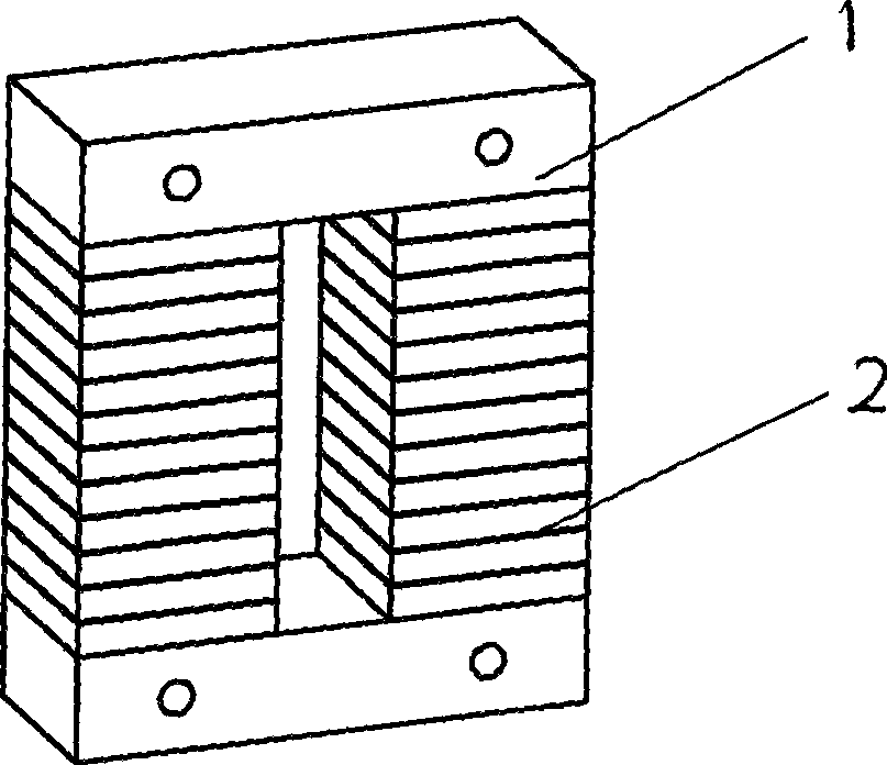
[0027] In the inductor core of the present invention, the iron yoke is made of non-oriented silicon steel sheet, and the core column is made of stacked rectangular ferrite magnetic sheets, such as Figure 1 shown. The loss is reduced to about 245W, the loss is reduced by 53%, and the temperature rise is significantly reduced, which meets the design requirements.

Embodiment 2

[0028] Example 2 Freewheeling Inductor of PWM Rectifier with Composite Iron Core of Silicon Steel Sheet and Iron Powder Core

[0029] PWM rectifier freewheeling inductance:

[0030] Current: 60A, inductance: 1.1mH, and current harmonics of 9.8kHz and other frequencies are about 12.5A.

[0031] In the prior art, the laminated iron core made of 0.18mm cold-rolled grain-oriented silicon steel sheet has a loss of about 280W and a high temperature rise, which cannot meet the design requirements.

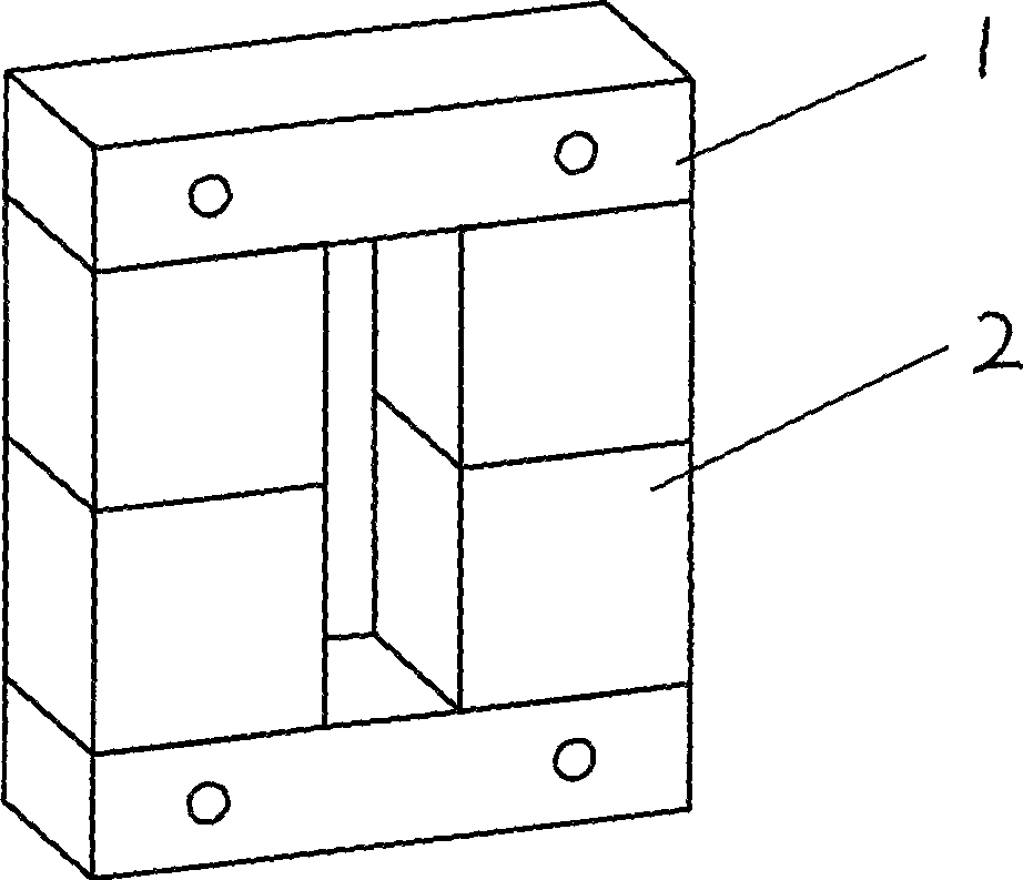
[0032] Inductance iron core of the present invention, its iron yoke is 0.23mm cold-rolled grain-oriented silicon steel sheet, and iron core post uses rectangular iron powder core, as Figure II shown. The loss is reduced to about 165W, the loss is reduced by 41%, and the temperature rise is significantly reduced, which meets the design requirements.


PUM


Abstract

The invention relates to a novel inductance core, consisting of a yoke iron and a core limb; the inductance core is characterized in that the yoke iron and the core limb are made of different soft magnetic materials. The novel inductance core uses different soft magnetic materials to be composed to prepare the yoke iron and the core limb of the inductance core; wherein, the yoke iron is preferably made of the soft magnetic material such as silicon steel which has greater strength, is easy to be welded and punched and is economical; the core limb is preferably made of materials such as soft magnetic ferrite or metal soft magnetic powder core which have extremely low loss during high frequency and light weight, are convenient to be processed into blocks with small dimension, can generate a plurality of air gaps during the overlapping process and are convenient for processing the air gaps at the same time. The inductance core has the advantages of simple and firm yoke iron, low loss of core limb, dispersed air gaps, extremely low loss generated by diffusion magnetic field, high efficiency, low loss, light weight, and the like.

Description

technical field [0001] The invention relates to an inductive device with an iron core used in power electronic equipment, in particular to a new type of inductance iron core. Background technique [0002] In power electronic equipment, it is necessary to use an inductive device with an iron core to achieve the purpose of the circuit designer, such as filtering, energy storage, etc. At present, the commonly used inductor cores all use the same material to make the iron yoke and iron core column. Because different soft magnetic materials have different physical properties, such as [0003] Silicon steel materials have the advantages of high mechanical strength, easy welding and punching, and low material cost. At the same time, it also has the advantages of high magnetic permeability and high saturation magnetic flux density, but its disadvantages are that, on the one hand, silicon steel materials have higher core loss in the occasion where the current contains rich high-orde...

Claims


Application Information

Patent Timeline
IPC IPC(8): H01F27/24H01F1/14H01F1/34H01F41/02
Inventor 焦海波
Owner 焦海波
Learn More