Compressor and permanent magnet motor thereof

A technology of permanent magnet motors and magnetic parts, applied in the direction of electromechanical devices, magnetic circuits, electric components, etc., can solve the problems of large vibration noise and small vibration noise, and achieve the goal of reducing airflow noise, vibration noise, and motor noise Effect

Pending Publication Date: 2017-06-09
GUANGDONG MEIZHI COMPRESSOR
View PDF4 Cites 7 Cited by
  • Summary
  • Abstract
  • Description
  • Claims
  • Application Information

AI Technical Summary

Problems solved by technology

[0004] The purpose of the present invention is to provide a permanent magnet motor which can still maintain relatively small vibration and noise under high speed conditions in order to overcome the problem of high vibration and noise of the permanent magnet motor in the prior art. The invention also provides a compressor with the permanent magnet motor

Method used


Image

  • Compressor and permanent magnet motor thereof
  • Compressor and permanent magnet motor thereof
  • Compressor and permanent magnet motor thereof

Examples


Embodiment Construction

[0032] In the present invention, it should be understood that the orientation or positional relationship indicated by the terms "inner", "outer", "axial", "radial", "circumferential" etc. is based on the orientation or position shown in the drawings relationship, and also corresponds to the orientation or positional relationship actually used, is only for the convenience of describing the present invention and simplification of the description, and does not indicate that the device or element referred to must have a specific orientation, be constructed and operated in a specific orientation, and therefore cannot be construed as a limitation of the invention.

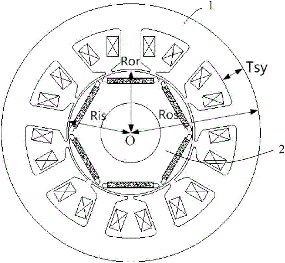
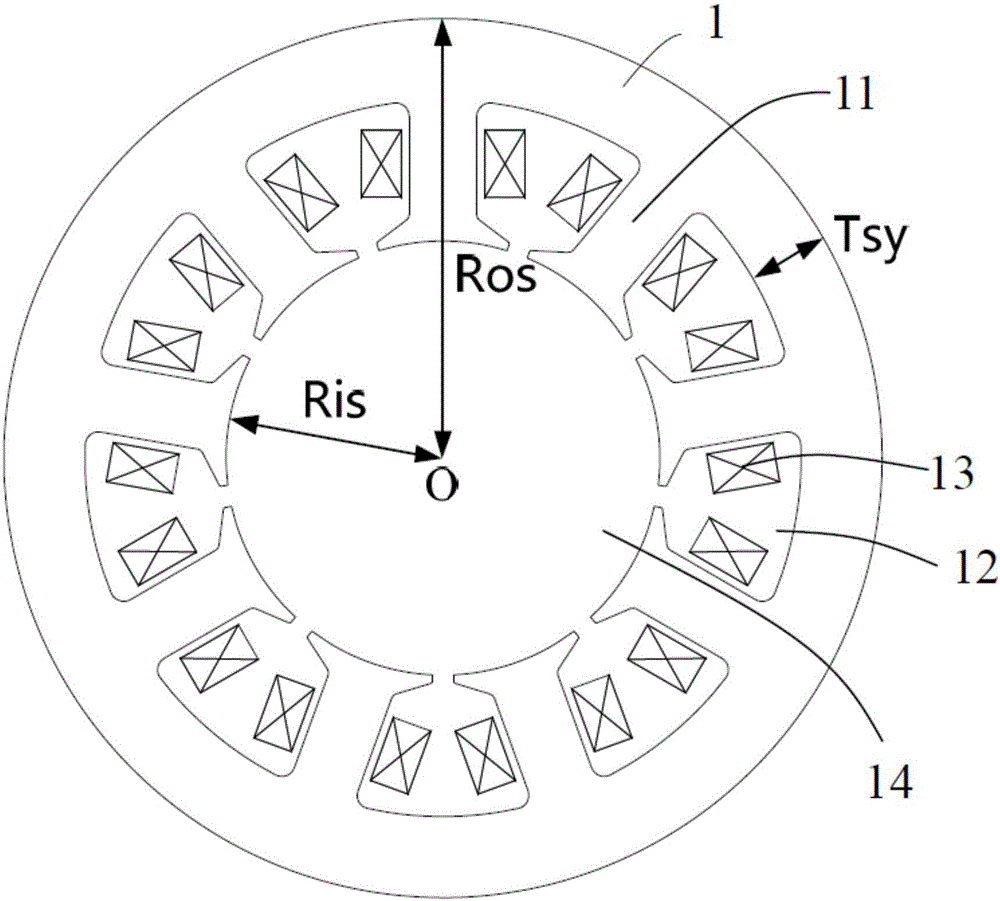
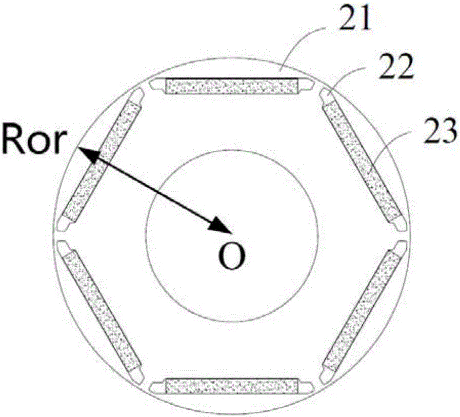
[0033] The invention provides a permanent magnet motor, combined with Figure 1 to Figure 3 , The permanent magnet motor of the present invention includes a stator 1 and a rotor 2, the stator 1 includes a stator core and a stator winding 13, the stator core includes a plurality of stator teeth 11 distributed along the ci...


PUM


Abstract

The invention relates to the field of motors and discloses a compressor and a permanent magnet motor thereof. The permanent magnet motor comprises a stator and a rotor, wherein the stator comprises a stator core and a stator winding; the stator core comprises multiple stator teeth, stator slots and a rotor containing part; the stator teeth are distributed in the peripheral direction of the stator at intervals; each stator slot is formed between two adjacent stator teeth; the rotor containing part is defined by inner end edges of the multiple stator teeth; the stator winding is arranged in the stator slots; the rotor can be rotationally arranged in the rotor containing part relative to the stator; the rotor comprises a rotor core; multiple magnet slots are formed in the rotor core in the peripheral direction at intervals; the rotor further comprises multiple magnetic parts which are respectively arranged in the multiple magnet slots; the distance between the rotation center of the rotor and an outer edge of the rotor containing part is Ris; the distance between the rotation center of the rotor and an outer edge of the rotor core is Ror; Ris-Ror is greater than or equal to 0.9 mm and less than or equal to 2.2 mm.

Description

technical field [0001] The invention relates to the field of motors, in particular to a permanent magnet motor and a compressor with the permanent magnet motor. Background technique [0002] In the existing permanent magnet synchronous motors for rotary compressors, in order to improve the energy efficiency of the motor and improve the material utilization rate, the air gap between the stator and the rotor is usually designed to be small, but when this permanent magnet motor is used for high In the running state of high speed, affected by factors such as air gap magnetic field harmonics and rotor static eccentricity caused by assembly, the motor is subjected to high-frequency radial electromagnetic force and unilateral electromagnetic force, resulting in greater vibration and noise. [0003] Therefore, it is urgent to design a permanent magnet motor with less vibration and noise and suitable for higher speed operation. Contents of the invention [0004] The purpose of the...

Claims


Application Information

Patent Timeline
Patent Type & Authority Applications(China)
IPC IPC(8): H02K1/27H02K1/16
CPCH02K1/16H02K1/2706H02K2213/03H02K2201/03
Inventor 徐飞王正祥邱小华
Owner GUANGDONG MEIZHI COMPRESSOR
Why Eureka
Try Eureka