Multi-way rotor control valve

A technology for controlling valves and rotors, applied in multi-port valves, valve details, valve devices, etc., can solve the problems of many control unit lines, high hardware investment cost, large size, etc., and achieve diversified functions, convenient control, and small size. Effect

Inactive Publication Date: 2018-12-25
GUANGDONG MECHANICAL & ELECTRICAL COLLEGE
View PDF9 Cites 14 Cited by
  • Summary
  • Abstract
  • Description
  • Claims
  • Application Information

AI Technical Summary

Problems solved by technology

For example, if a water pump is used to supply water regularly and quantitatively to four incubators for growing vegetables, the existing technology must be equipped with four water supply solenoid valves for control, resulting in many and complicated water supply channels and control unit circuits, large volume, and high hardware investment costs.

Method used


Image

  • Multi-way rotor control valve
  • Multi-way rotor control valve
  • Multi-way rotor control valve

Examples


Embodiment 1

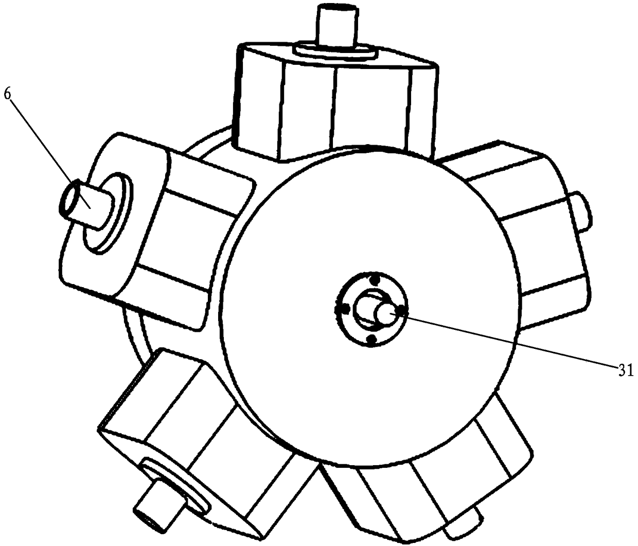
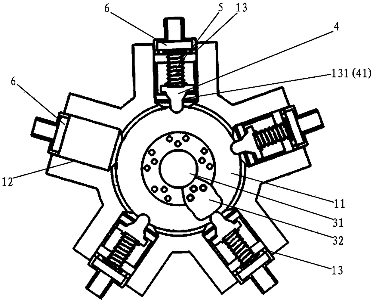
[0034] see Figure 1 to Figure 6 , this embodiment relates to a control valve, including a valve body 1, a valve cover 2, a rotating mechanism 3, a valve core 4, an elastic member 5 and a connecting seat 6, the rotating mechanism 3 is rotatably mounted on the valve body 1, and the valve A built-in cavity 11 is provided on the body 1, and a first through hole 12 and a plurality of second through holes 13 communicating with the built-in cavity 11 are opened on the circumferential direction of the valve body 1, and the valve cover 2 is sealed and closed. On the built-in cavity 11; the valve core 4 is slidably installed in the second through hole 13, the opening end of the second through hole 13 is provided with an internal thread, and the connecting seat 6 is connected by a thread Installed at the opening end of the second through hole 13, the two ends of the elastic member 5 respectively press the valve core 4 and the connecting seat 6 to press the valve core 4 to the inner cavi...

Embodiment 2

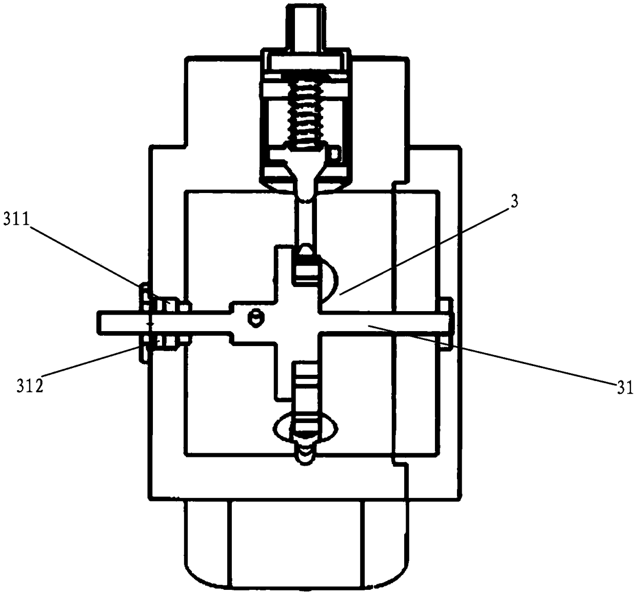
[0048] This embodiment is based on Embodiment 1, as an improvement to the structure of the rotating shaft and valve cover, such as Figure 8 to Figure 10 As shown, one end of the rotating shaft 31 is installed on the valve body 1 through a bearing 311 to form a cantilever support structure, and the rotating shaft 31 is sealed and connected with the valve body 1 through a seal 312; A third through hole 21 is opened, and the third through hole 21 is a water inlet or a water outlet. The control valve of this structure adds a third through hole 21 on the basis of Embodiment 1, so that figure 2 The control structure of one input and four outputs or four inputs and one output can realize the control structure of one input and five outputs or five inputs and one output without increasing the volume of the valve body, which increases the control range and is more convenient to use And flexible, it not only improves the number of control loops, but also prevents the increase of the v...


PUM


Abstract

The invention discloses a multi-way rotor control valve which comprises a valve body, a valve cover, a rotating mechanism, a valve core, an elastic member and a connecting seat. The valve body is provided with a built-in cavity, and a first through hole and a plurality of second through holes, communicating with the built-in cavity, are formed in the valve body in a circumferential direction; thevalve core is slidably mounted in the second through hole, and the connecting seat is installed at the opening end of the second through hole in a threaded connecting mode; the rotating mechanism includes or rotates a rotating shaft mounted on the valve body, one end of the rotating shaft is fixedly mounted on a rotating shaft cam, when the rotating shaft rotates, the other end of the rotating shaft cam periodically opens the valve core to connect the built-in cavity with the second through hole; the first through hole is a water inlet or a water outlet, and the water outlet or the water inletis formed in the connecting seat to form a one inlet and multiple outlets control valve structure, or a one outlet and multiple inlets control valve structure. According to the multi-way rotor control valve, a function of supplying the multi-channel fluid circuit in turn through a control valve is realized, a control structure is greatly simplified, structure is simple, control is convenient, andthe input cost of hardware is reduced.

Description

technical field [0001] The invention relates to the technical field of flow control, in particular to a control valve, in particular to a multi-way rotor control valve. Background technique [0002] In industrial and agricultural production, it is often necessary to automatically transport fluids such as liquids and gases in multiple channels. The existing related automatic technologies mainly use controllers based on electromagnetic valves, such as hydraulic electromagnetic reversing valves, pneumatic electromagnetic reversing valves, water supply electromagnetic valve switches, etc. , basically adopt the idea of ​​one way one control valve. In fact, in production, sometimes it is only necessary to alternately deliver fluid to various channels intermittently, and many electromagnetic valves must be provided by using the prior art. For example, if a water pump is used to supply water regularly and quantitatively to four incubators for growing vegetables, the existing techno...

Claims


Application Information

Patent Timeline
Patent Type & Authority Applications(China)
IPC IPC(8): F16K11/16F16K31/524
CPCF16K11/163F16K31/52416
Inventor 陈孝平漆军陈榕福罗耀余声许叶康智
Owner GUANGDONG MECHANICAL & ELECTRICAL COLLEGE
Why Eureka
Try Eureka