Unlock instant, AI-driven research and patent intelligence for your innovation.

Air inlet and outlet structure of integrated kitchen air conditioner

An integrated technology of air inlet and outlet, applied in the field of kitchen air conditioners, can solve the problems of poor use effect, inconvenient installation, and difficult installation, etc., and achieve the effect of good use effect and small installation space

Pending Publication Date: 2018-12-25
JIAXING CITY DINGYUE ELECTRICAL APPLIANCE SCI& TECH
View PDF0 Cites 1 Cited by
  • Summary
  • Abstract
  • Description
  • Claims
  • Application Information

AI Technical Summary

Problems solved by technology

At present, most of the existing air conditioners are of separate design, that is, the inner unit of the air conditioner and the outer unit of the air conditioner are independently designed and installed separately. This kind of air conditioner is expensive and is difficult to install due to the limitation of the installation space of the kitchen.
Therefore, some integrated kitchen air conditioners gradually appear on the market. At present, the existing integrated kitchen air conditioners generally include an air conditioner panel and an installation shell. The air conditioner panel is installed below the installation shell. The air blown out of the air outlet is sucked in by the air inlet, so it is usually required to have a certain distance between the two air outlets, and the air inlet and the air outlet are set separately, which leads to the current kitchen air conditioner requiring a higher installation space in the kitchen. The use effect is poor for small-area kitchens; in addition, the air outlet and air inlet are set separately, and it is necessary to arrange pipes in two locations during specific installation, which is very inconvenient to install

Method used


Image

  • Air inlet and outlet structure of integrated kitchen air conditioner
  • Air inlet and outlet structure of integrated kitchen air conditioner
  • Air inlet and outlet structure of integrated kitchen air conditioner

Examples


Embodiment Construction

[0025] The present invention will be further described in detail below in conjunction with the accompanying drawings and embodiments.

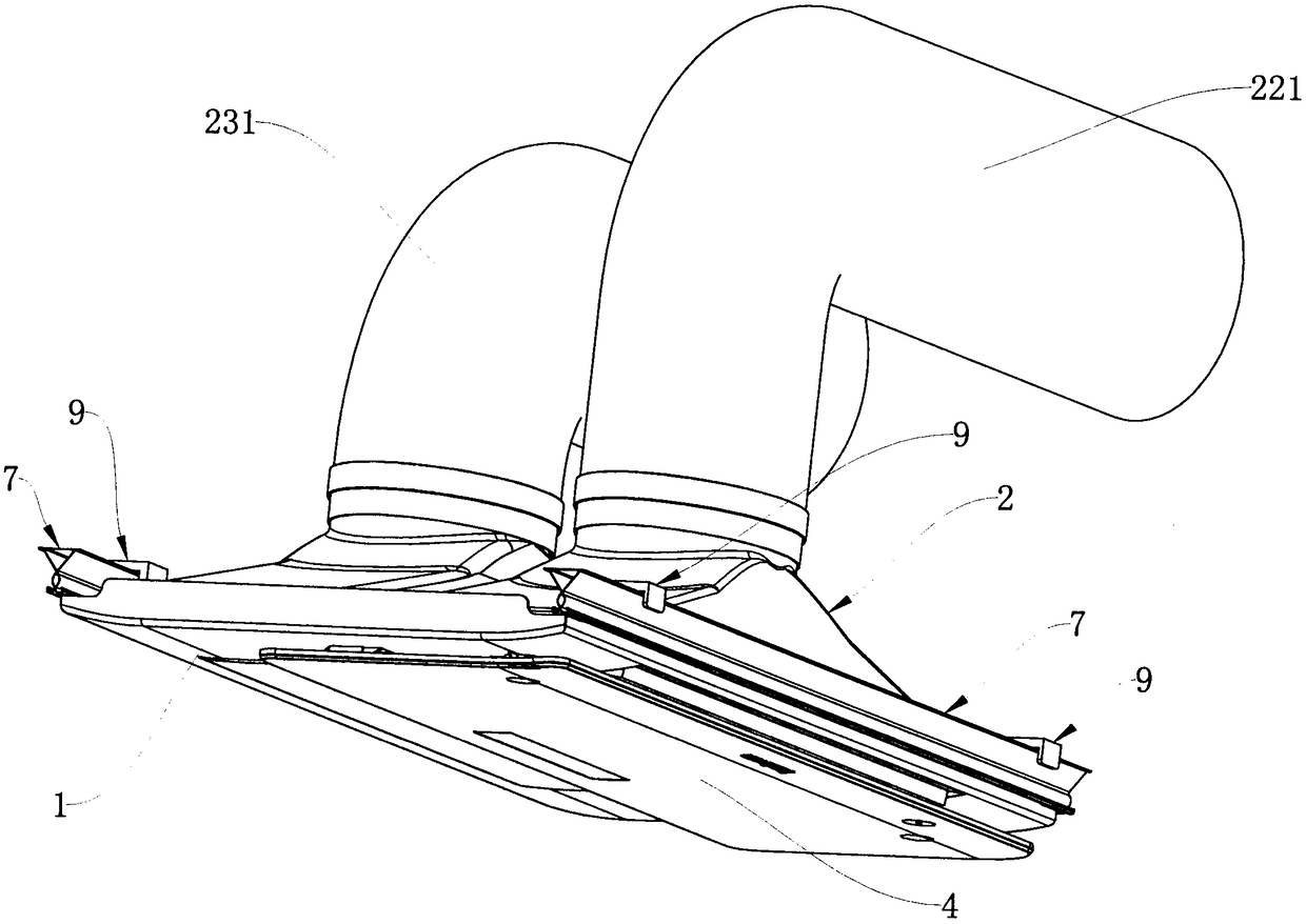
[0026] like Figure 1 to Figure 7 As shown, an air inlet and outlet structure of an integrated kitchen air conditioner includes an air conditioner panel 1, an air inlet and outlet air splitter 2 is arranged on the air conditioner panel 1, and the inlet and outlet air splitter 2 includes a base plate 21, and upper and lower through The air inlet hole (not shown in the figure) and the air outlet hole (not shown in the figure), the air inlet hole is provided with the air inlet hood 22 that penetrates up and down, and the air outlet hole is provided with the air outlet hood 23 that penetrates up and down. The bottom end faces of the wind cover 22 and the air outlet cover 23 are sealed and bonded to the upper end face of the air-conditioning panel 1. The air-conditioning panel 1 is provided with an air inlet 11 and an air outlet 12 that penetrate u...


PUM


Abstract

The invention discloses an air inlet and outlet structure of an integrated kitchen air conditioner. The air inlet and outlet structure comprises an air conditioner panel, and is characterized in thatan air inlet and outlet air flow divider is arranged on the air conditioner panel and comprises a base plate; an air inlet and an air outlet which vertically communicate are formed in the base plate in a spaced mode; a vertically-communicating air inlet cover is arranged on the air inlet, and a vertically-communicating air outlet cover is arranged on the air outlet; the bottom end faces of the airinlet cover and the air outlet cover are attached to the upper end face of the air conditioner panel in a sealed mode; an air inlet and an air outlet which vertically communicate are formed in the air conditioner panel in a spaced mode; the air inlet cover is arranged above the air inlet in a covering mode, and the air outlet cover is arranged above the air outlet in a covering mode; and a swinging blade capable of vertically swinging is arranged in the air outlet cover. The air inlet and outlet structure has the advantages of being simple, convenient to mount, small in occupied mounting space and also good in overall using effect.

Description

technical field [0001] The invention relates to a kitchen air conditioner, in particular to an air inlet and outlet structure of an integrated kitchen air conditioner. Background technique [0002] With the improvement of living standards, people's requirements for the quality of life are getting higher and higher. Cooking in a high-temperature kitchen in hot summer has become a kind of suffering, so kitchen air conditioners came into being. At present, most of the existing air conditioners are of separate design, that is, including the air conditioner internal unit and the air conditioner external unit, which are independently designed and installed separately. This type of air conditioner is expensive and is difficult to install due to the limitation of the installation space of the kitchen. Therefore, some integrated kitchen air conditioners gradually appear on the market. At present, the existing integrated kitchen air conditioners generally include an air conditioner pa...

Claims


Application Information

Patent Timeline
Patent Type & Authority Applications(China)
IPC IPC(8): F24F13/00F24F13/06F24F13/14F24F13/28F24F13/20F24F13/02F24C15/20
CPCF24C15/2035F24F13/00F24F13/02F24F13/06F24F13/14F24F13/20F24F13/28
Inventor 王效春
Owner JIAXING CITY DINGYUE ELECTRICAL APPLIANCE SCI& TECH