Device for distributing optical fibers on steel rail

A rail and optical fiber technology, applied in the direction of optical fiber/cable installation, etc., can solve the problems of low efficiency, no optical fiber cloth, easy missed detection and false detection, etc., to achieve the effect of convenient deployment and improved deployment efficiency

Inactive Publication Date: 2011-11-16
INST OF SEMICONDUCTORS - CHINESE ACAD OF SCI
View PDF7 Cites 3 Cited by
  • Summary
  • Abstract
  • Description
  • Claims
  • Application Information

AI Technical Summary

Problems solved by technology

This method is inefficient and prone to missed detection and false detection
Another method is to use rail inspection cars, but the rail inspection cars are expensive and run at a speed much lower than the conventional speed of railway trains, especially for high-speed railways, rail inspection cars will seriously affect the normal operation of the railway
However, there is no report on the device for laying optical fiber on the rail

Method used


Image

  • Device for distributing optical fibers on steel rail
  • Device for distributing optical fibers on steel rail
  • Device for distributing optical fibers on steel rail

Examples


Embodiment Construction

[0028] In order to make the object, technical solution and advantages of the present invention clearer, the present invention will be described in further detail below in conjunction with specific embodiments and with reference to the accompanying drawings.

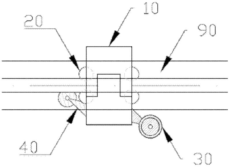
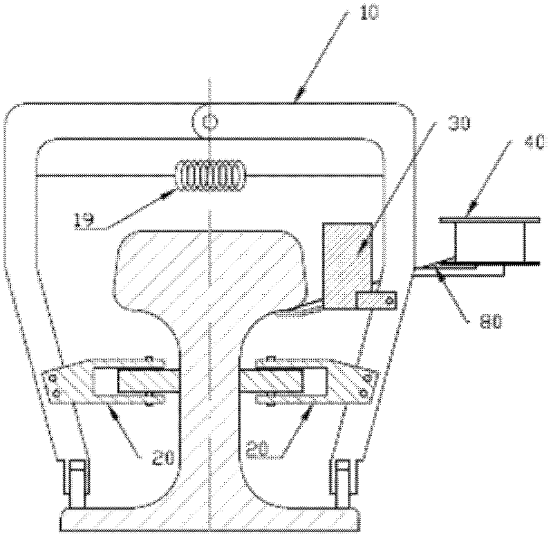
[0029] Such as Figure 1 ~ Figure 2 as shown, figure 1 It is a top view of a device for laying optical fibers on rails according to an embodiment of the present invention. figure 2 It is a view along the cross section of the rail of the device for laying optical fibers on the rail according to the embodiment of the present invention. The device for laying optical fibers on rails provided by the present invention includes: a main body support 10, a running device 20 for walking on the measured steel rail 90 and installed on the main body support 10, a glue injection pressing device 30 and an optical fiber feeding device 40 .

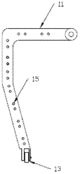
[0030] The body frame 10 is composed of two L-shaped beams 11 connected to each other. imag...


PUM


Abstract

The invention discloses a device for distributing optical fibers on a steel rail. The device comprises a main body bracket (10), a walking device (20) used for walking on the steel rail to be measured and arranged on the main body bracket (10), a glue-injecting pressing device (30) and an optical fiber feeding device (40). According to the device for distributing the optical fiber on the steel rail, disclosed by the invention, convenient distribution of the optical fibers on the steel rail is realized through arranging the glue-injecting pressing device and the optical fiber feeding device, and distribution efficiency can be increased through the walking device.

Description

technical field [0001] The invention relates to the technical field of optical fiber sensing, in particular to a device for arranging optical fibers on steel rails. Background technique [0002] Rail transit is an important form of transportation, including urban light rail transit, subway, high-speed railway, heavy-duty railway, etc. With the rapid development of my country's rail transit, the transportation capacity and volume continue to increase, and the damage of rails is also increasing. Rail head peeling, corrugation, and side grinding are some of the most typical forms of rail damage. [0003] At present, there are two types of rail damage detection methods, one is manual detection. Through the inspection along the track by the workers of the railway works section, the degree of damage to the rail is checked by visual judgment and special measuring devices. This method is inefficient and prone to missed detection and false detection. Another method is to use rail...

Claims


Application Information

Patent Timeline
IPC IPC(8): G02B6/46
Inventor 张文涛李芳
Owner INST OF SEMICONDUCTORS - CHINESE ACAD OF SCI
Why Eureka
Try Eureka