A low-voltage withdrawable switchgear push interlock mechanism

A low-voltage withdrawable, interlocking mechanism technology, applied in the direction of pull-out switchgear, switchgear, electrical components, etc., can solve the problems of affecting the normal power supply use of the switchgear, prone to breakage, large temperature impact, etc., to avoid breakage The effect of failure, easy operation and reduction of failure rate

Active Publication Date: 2020-01-10
瑞安市华泰电器厂
View PDF1 Cites 3 Cited by
  • Summary
  • Abstract
  • Description
  • Claims
  • Application Information

AI Technical Summary

Problems solved by technology

[0005] However, the groove-shaped positioning parts are usually made of plastic material, which is greatly affected by temperature, especially in extremely cold countries and regions, where it is prone to breakage and seriously affects the normal power supply of the switchgear.
If the groove-shaped positioning parts are made of more reliable metal materials such as iron, not only the processing is difficult, but also the cost is high, which is not a reasonable choice

Method used


Image

  • A low-voltage withdrawable switchgear push interlock mechanism
  • A low-voltage withdrawable switchgear push interlock mechanism
  • A low-voltage withdrawable switchgear push interlock mechanism

Examples


Embodiment Construction

[0025] Embodiments of the present invention will be further described below in conjunction with accompanying drawings:

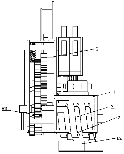
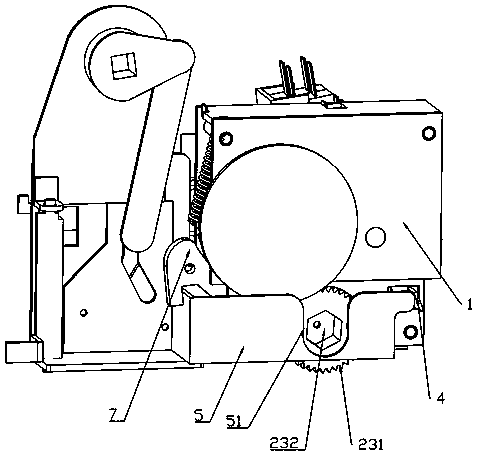
[0026] Such as figure 1 As shown, a low-voltage withdrawable switchgear push interlock mechanism includes a mounting bracket 1, a pushing mechanism 2, and a position positioning mechanism 3; the mounting bracket 1 is fastened together by bolts from a front bracket, a middle bracket, and a rear bracket. , to facilitate product assembly.

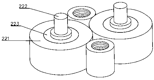
[0027] Such as Figure 1-2 As shown, the propulsion mechanism 2 is installed on the installation bracket 1, and is used to push the drawer to move in the cabinet. The screw rod 21 is fitted with a roller bearing locator 22 that pushes the drawer to move back and forth.

[0028] Wherein, the driving screw 21 and the roller bearing positioning member 22 are both made of iron material, so that they are less affected by the ambient temperature, the structure is more stable, and the occurrence of fracture failures is effective...


PUM


Abstract

A low-voltage draw-out switch cabinet propel interlocking mechanism is characterized in that a transmission screw and a roller bearing positioning part are metal parts; the roller bearing positioningpart comprises a fixed base and at least two vertically arranged rollers, wherein the rollers are arranged in a forward and backward interval along the axial direction of the transmission screw, the lower end of the roller is rotatably mounted on the fixed base through a bearing, and the upper end can extend into the spiral groove of the transmission screw and be drivingly matched with the transmission screw. The mechanism has the advantages that the positioning parts of the transmission screw and the roller bearing are all made of ferrous material, so that the positioning parts are less influenced by the ambient temperature, the structure is more stable, and the fracture fault is effectively avoided. Moreover, the roller bearing positioning part is simple in structure and convenient to assemble. When the roller is matched with the screw spiral groove of the transmission screw, the roller itself will rotate, which not only makes the operation easier, but also ensures that the roller bearing positioning part will not be stuck.

Description

technical field [0001] The invention relates to a low-voltage draw-out switchgear, in particular to a low-voltage draw-out switch cabinet propulsion interlocking mechanism. Background technique [0002] In modern distribution network and engineering construction, withdrawable low-voltage distribution cabinets are widely used in power distribution systems in power plants, substations, factories and mines, and high-rise buildings. Due to its special working characteristics, the power distribution industry has strict requirements on the design of power distribution cabinets. [0003] The national standard GB7251 stipulates that in the withdrawable low-voltage power distribution cabinet, the drawer of each circuit should have an operating mechanism for advancing and withdrawing in the three positions of connection, test and isolation. The mechanism should be able to advance and withdraw freely in the corresponding position, and the position should be self-locking. [0004] For...

Claims


Application Information

Patent Timeline
Patent Type & Authority Patents(China)
IPC IPC(8): H02B11/133
CPCH02B11/133
Inventor 李秀荣项赫男
Owner 瑞安市华泰电器厂
Why Eureka
Try Eureka