A stator iron core structure of a hydrogenerator and a molding method thereof

A hydroelectric generator, stator core technology, applied in the direction of magnetic circuit shape/style/structure, magnetic circuit static parts, etc., can solve the difficulty and disadvantage of increasing the processing and assembly technology of hydroelectric generator stator core structure Problems such as long-term safe and stable operation of the hydroelectric generator set, broken teeth, etc., have achieved the effect of meeting the operating conditions and technical requirements, increasing the difficulty of processing technology, and increasing the difficulty of assembly technology

Pending Publication Date: 2018-12-25
DONG FANG HENG YUN ELECTRICAL MACHINERY
View PDF0 Cites 1 Cited by
  • Summary
  • Abstract
  • Description
  • Claims
  • Application Information

AI Technical Summary

Problems solved by technology

Although this kind of stator core structure meets the technical requirements of processing, assembly and use conditions, it is inconsistent due to the inconsistency of the bearing force of the tensioning screws distributed in the circumferential direction, especially the silicon steel sheets of large-scale hydro-generators are fan-shaped and non-uniform. The full-circle forming structure, the split stacking structure between adjacent silicon steel sheets, and the fan-shaped non-full-circle forming structure of the finger plate that transmits the axial locking force make the axial locking force of the stator core structure increase with the service time. Due to the vibration of electromagnetic, mechanical and other forces, the axial locking force borne by the end of the stator core structure is differentiated in the circumferential direction. This difference will bring the stator core structure in the stator frame. Technical problems such as looseness, broken teeth, coil wear, coil blasting, etc., will even cause serious accidents such as stator core burnout, which is not conducive to the long-term, safe and stable operation of the hydro-generator set
[0004] If the silicon steel sheet at the end of the stator core structure of the hydroelectric generator and the finger pressure plates at both ends of the stator frame are directly formed in a round overall structure in the circumferential direction, the axial locking force will be enhanced in the circumferential direction. The balanced application of the stator core structure ensures the firm and stable long-term assembly quality of the stator core structure on the stator base, so as to improve the long-term safe and stable operation of the hydro-generator set; however, this will increase the stator iron of the hydro-generator. The processing and assembly technology of the core structure is difficult, and may even fail to meet the technical requirements of the working conditions

Method used


Image

  • A stator iron core structure of a hydrogenerator and a molding method thereof

Examples


Embodiment 1

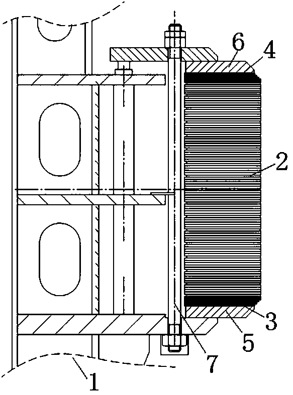
[0025] see figure 1 As shown, the stator core structure of the present invention includes several silicon steel sheets, each silicon steel sheet is a fan-shaped non-circular structure, and the thickness of each silicon steel sheet is about 0.5mm. These silicon steel sheets are divided into excitation end iron core assembly 4, middle iron core assembly 2, water machine end iron core assembly 3, excitation end iron core assembly 4 and water machine end iron according to the arrangement position on the stator frame 1. The core assembly 3 is located at both axial ends of the middle iron core assembly 2 .

[0026] Among them, the excitation end iron core assembly 4 assembled in the excitation end area of ​​the stator frame 1 is composed of silicon steel sheets arranged in order according to the conventional design requirements, and arranged and bonded to form an overall ring structure. The thickness of the iron core assembly 4 at the excitation end is determined by bonding and com...

Embodiment 2

[0041] The stator core structure of the present invention includes several silicon steel sheets, each silicon steel sheet is fan-shaped and non-circular in structure, and the thickness of each silicon steel sheet is about 0.5 mm. These silicon steel sheets are divided into excitation end iron core assembly, middle iron core assembly and water machine end iron core assembly according to the arrangement position on the stator frame. The excitation end iron core assembly and water machine end iron core assembly are located in The axial ends of the middle iron core assembly.

[0042] Among them, the excitation end iron core assembly assembled in the excitation end area of ​​the stator frame is composed of silicon steel sheets arranged in order according to the conventional design requirements, and arranged and bonded into an overall ring structure. The thickness of the iron core assembly at the excitation end is determined by bonding and combining about 150 layers of the above-men...

Embodiment 3

[0057]The stator core structure of the present invention includes several silicon steel sheets, each silicon steel sheet is a full circle structure, and the thickness of each silicon steel sheet is about 0.5 mm. These silicon steel sheets are divided into excitation end iron core assembly, middle iron core assembly and water machine end iron core assembly according to the arrangement position on the stator frame. The excitation end iron core assembly and water machine end iron core assembly are located in The axial ends of the middle iron core assembly.

[0058] Among them, the excitation core assembly assembled in the excitation end area of ​​the stator frame is made of silicon steel sheets with a thickness of 0.5 mm arranged in accordance with the conventional design requirements, and the arrangement and bonding combination is an overall ring shape with a thickness of about 25 mm. structure. The thickness of the iron core assembly at the excitation end is determined by bond...


PUM

PropertyMeasurementUnit
thicknessaaaaaaaaaa
thicknessaaaaaaaaaa
thicknessaaaaaaaaaa

Abstract

The invention discloses a stator iron core structure of a hydrogenerator and a molding method thereof. The stator iron core structure comprises a plurality of silicon steel sheets; according to the arrangement position of the silicon steel sheets on a stator base, the silicon steel sheets are divided into a middle iron core assembly and end iron core assemblies at the two axial ends; each siliconsteel sheet of the end iron core assembly is bonded and assembled into an integral annular structure according to the arrangement order, the silicon steel sheets of the middle iron core assembly are stacked and arranged between the end iron core assemblies of the integral annular structure at both ends in the arrangement order, and the end core assemblies at both ends respectively bear the axial locking force of the stator core pressing mechanism to the stator core structure in the axial direction. The present invention not only does not obviously increase the technical difficulty of processing and assembling the stator iron core structure, but also can meet the technical requirements of the service condition, and can effectively solve the technical problem that the axial locking force ofthe stator iron core structure on the stator frame is liable to be destroyed, which is favorable for the long-term safe and stable operation of the hydrogenerator.

Description

technical field [0001] The invention relates to a hydraulic generator, in particular to a new stator core structure of a hydraulic generator and a forming method of the stator core structure. Background technique [0002] The stator of the hydro-generator is the static part of the hydro-generator. It is mainly composed of the stator frame and the iron core and windings assembled on the stator frame. And the necessary electromagnetic part of the current path. [0003] The stator core structure of a hydroelectric generator is composed of a number of silicon steel sheets stacked on the stator frame according to the set arrangement sequence, especially the stator core structure of a large-scale hydroelectric generator. , each layer of silicon steel sheets is composed of several fan-shaped silicon steel sheets in a circumferential butt joint manner according to the set arrangement sequence. The stator core structure stacked and formed on the stator frame is fixed by the axial l...

Claims


Application Information

Patent Timeline
Patent Type & Authority Applications(China)
IPC IPC(8): H02K1/12
CPCH02K1/12
Inventor 黄容刘幹镶
Owner DONG FANG HENG YUN ELECTRICAL MACHINERY
Why Eureka
Try Eureka