

Pressure-reducing control valve for severe service conditions
a technology of severe service conditions and control valves, applied in the direction of multiple way valves, valve details, sliding valves, etc., can solve the problems of gas moving at supersonic speed, one or more valve stages can become choked, and the number of concentric sleeves is restricted to three, so as to increase the energy loss of flowing fluid
Inactive Publication Date: 2004-03-18
SAUDI ARABIAN OIL CO
View PDF0 Cites 38 Cited by
- Summary
- Abstract
- Description
- Claims
- Application Information
AI Technical Summary
Benefits of technology
[0023] The seal formed by the external surface of the rings in the sleeve with the internal surface of the disk stack is by metal-to-metal compression. In a preferred embodiment, the drag disk stack is typically a braised one-piece construction purchased from a commercial source. The inside diameter of the axial opening or channel is determined and the sleeve to be inserted is formed with the outside diameter of the sealing rings of a dimension that will permit its insertion into the disk stack following thermal treatment, and its expansion under ambient or operating conditions to provide an effective metal-to-metal seal between the respective surfaces to thereby prevent the axial flow of fluid between these elements.
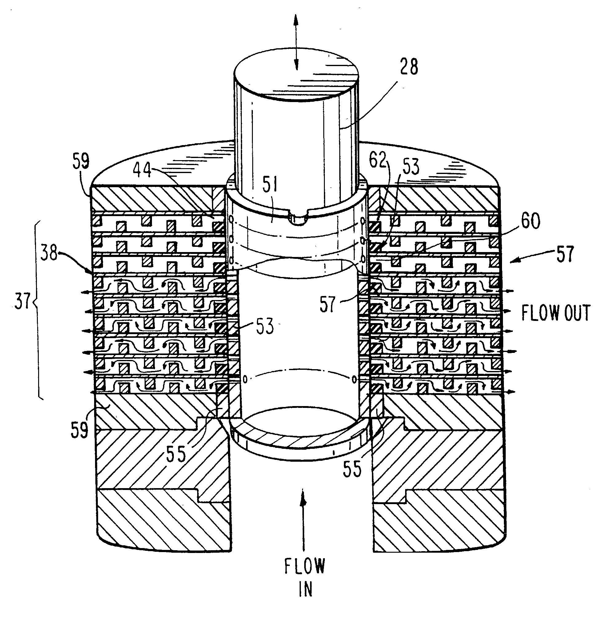
[0026] As will be understood by one of ordinary skill in the art, the pressure loss of the fluid can be increased by offsetting the alignment of the radial openings in the sleeve relative to the inlets in the adjacent stacked disks. A desirable pressure loss does occur due to the sudden expansion of the fluid as it exits the radial openings into the larger free volume defined by the projecting external ceiling rings that are formed in the surface of the sleeve.
[0030] In a further preferred embodiment, the first stage member can comprise two or more tubes or sleeves, each constructed as described above to further increase the energy loss of the flowing fluid.
Problems solved by technology
A principal drawback of this type of pressure reducing trim is that due to mechanical space limitations, the number of concentric sleeves is restricted to three or, at most, four.
Under severe conditions in gas service, with a sufficiently great fluid pressure differential, the gas moves at supersonic velocity and one or more stages of the valves can become choked.
This condition leads to excessive noise, vibration and deterioration of the fluid flow rate.
It is also known that the second and third stages in the valves of this configuration have limited pressure-reducing capability.
One limitation of the drag valve is that the metal disks are made from relatively soft materials, and when used in applications in which metallic particles or process debris are transported in the fluid, this debris can become imbedded in the inlet of the drag valve radial flow paths and as the plug is lowered to control the flow rate through the valve, extensive damage results to the valve trim.
The inlet passages are sheared and the plug can jam, rendering the valve inoperable.
Since the valve trim is one-piece braised assembly, repairs to damage are difficult and the replacement costs are high.
However, the pressure reduction capabilities are limited by choked flow produced by this device due to cavitation in liquid service and sonic velocity in gas applications.
As will be apparent, if the high pressure fluid contains metal particles or other process debris, the individual passages formed by the stacked disks will become clogged and effectively blocked so that the number of passages will be reduced over time.
Moreover, because of the relatively softer metals used in fabricating the disks 38, the impacted debris so deforms or otherwise damages the material that it cannot be repaired.
Method used
View moreImage
Smart ImageViewing Examples

Examples
example 2
[0060] A 24-inch valve trim of the invention is installed in a flare gas pipeline where the incoming gas is at 232 PSIG, with a flow rate of 232 million SCFD (Standard Cubic Feet / Day), at a temperature of 160.degree. F. Other characteristics of the gas are:
2 Molecular Weight 28.59 Compressibility 0.95 Flow Coefficient 880
[0061] The valve with about 14 stages of pressure reduction is required to provide a gas stream output at 5 PSIG with a sound pressure level of less than 85 dBA.
Login to View More PUM
 Abstract
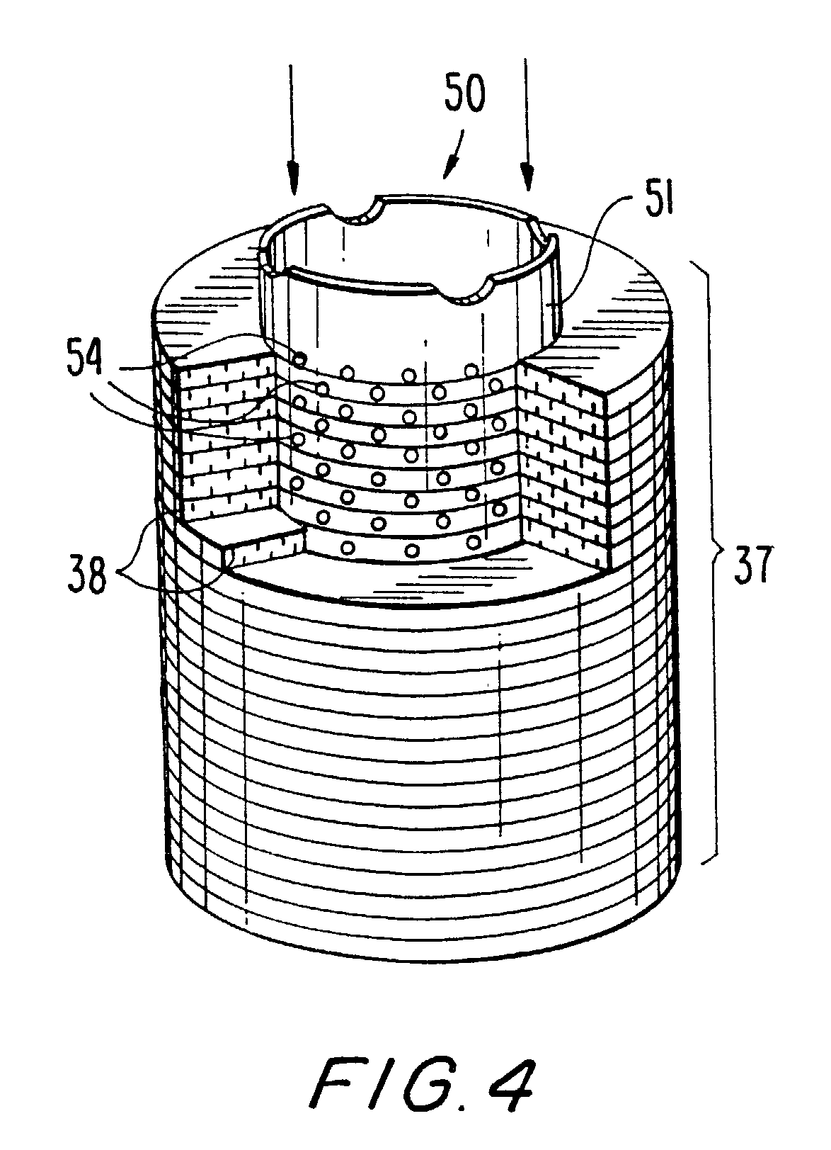
A severe service condition pressure reduction valve that is resistant to damage by debris carried by high-pressure process fluid stream and operates at acceptable noise levels includes a first stage annular member in the form of a tube or sleeve that is closely fitted into the axial annular opening of a disk stack trim or drag valve, the first stage member having a plurality of radial openings extending through the wall of the tube or sleeve that are aligned with, and correspond in radial and axial or longitudinal spacing to the flow paths in the disk stack valve. The external surface of the first stage member is provided with axially-spaced circumferential raised areas or rings that engage the internal surface of the disk stack annulus to prevent axial flow along the exterior surface of the sleeve.
Description
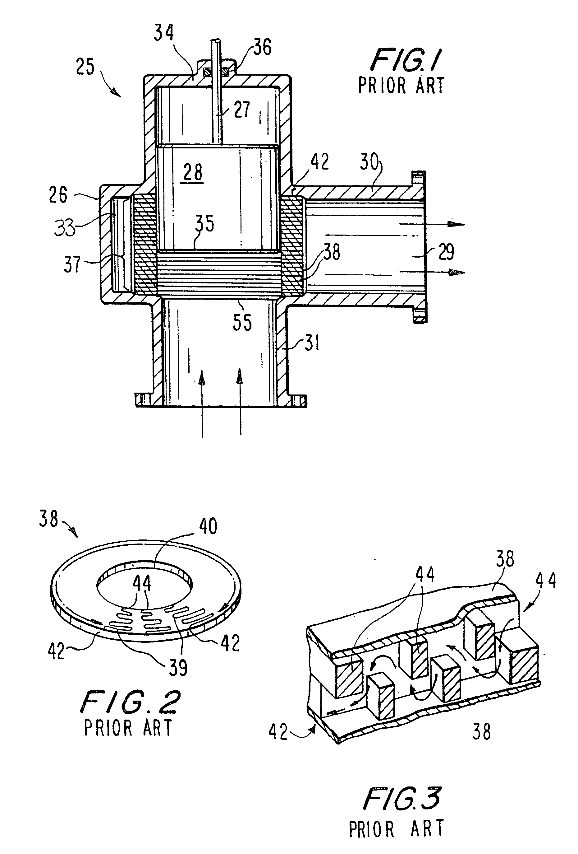
[0001] This invention relates to pressure reduction control valves used in the petroleum industry, and particularly to valves utilized on high pressure liquid and gas piping system that are rated for severe service.BACKGROUND IN THE ART[0002] In the severe service pressure-reducing control valve art, two distinct technologies have been available. Both technologies utilize an annular device that is inserted into the pipeline and a plug that causes the flow in the pipeline to be radially diverted from the axial flow path through a plurality of passages to be discharged from outlet ports in the exterior surface of the device to effect the reduction in pressure, after which the fluid flow is returned to a downstream pipeline.[0003] A pressure-reducing valve trim commonly referred to as the drilled hole cylinder also known as a single stage, multiple flow passage cartridge is in the form of an annular metal tube or sleeve, typically fabricated from 300 and 400 series stainless steel thro...
Claims
Login to View More Application Information
Patent Timeline
 Patent Type & AuthorityApplications(United States)
IPC IPC(8): F16K47/04F16K47/08
CPCF16K47/08F16K47/04Y10T137/86759Y10T137/86791Y10T137/86807
InventorNAWAZ, SHAH M.
OwnerSAUDI ARABIAN OIL CO