Method of using a support adjustment structure for pipe butt welding

A technology for adjusting structures and pipelines, applied in welding equipment, auxiliary welding equipment, welding/cutting auxiliary equipment, etc., can solve problems such as low alignment efficiency, difficulty, and slow down pipeline construction process

Active Publication Date: 2020-10-27
CHINA MCC5 GROUP CORP
View PDF6 Cites 0 Cited by
  • Summary
  • Abstract
  • Description
  • Claims
  • Application Information

AI Technical Summary

Problems solved by technology

[0002] On-site pipeline construction operations often involve the butt welding of a large number of pipelines. When the welding base pipeline is supported in the air by the support foundation, it is necessary to support the pipeline to be butt welded stably and reliably at the same height, and to ensure that the pipeline to be welded Only by aligning the ends of the welded base pipes with the ends of the welded foundation pipes can the butt welding quality of the two be guaranteed. The existing hoisting equipment can be used to suspend the pipes to be butt welded in the air, but it is difficult to control the alignment of the ends of the two , and the cost of using the existing hoisting equipment is high, and in the process of aligning the ends of the two, workers are required to assist in the control, the labor intensity of the workers is high, and the alignment efficiency is low, which slows down the entire pipeline construction process

Method used


Image

  • Method of using a support adjustment structure for pipe butt welding
  • Method of using a support adjustment structure for pipe butt welding
  • Method of using a support adjustment structure for pipe butt welding

Examples


Embodiment 1

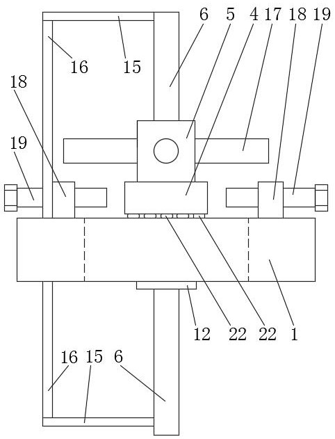
[0038] Such as Figures 1 to 6 As shown, the supporting adjustment structure for pipe butt welding,

[0039] It includes a support seat 1, at least three support rods 2, a pressure block 3, a lateral adjustment block 4, an adjustment sleeve 5 and an adjustment screw 6;

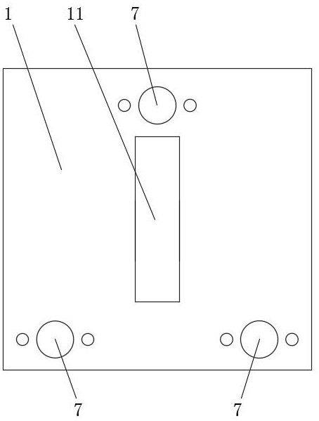
[0040] The bottom of the support seat 1 is provided with a semicircular groove 7, and the number of the semicircular groove 7 is the same as that of the support rod 2. The top of the support rod 2 has a mounting sphere 8, and the mounting sphere 8 is installed in the semicircular groove 7. The briquetting block 3 is provided with a through hole 9. The inner surface of the hole 9 is a spherical surface 10, the pressing block 3 is set on the lower half of the installation sphere 8 through the through hole 9, the pressing block 3 and the support seat 1 are fixedly connected by bolts, and the installation sphere 8 is pressed into the semicircular groove 7 , the installation sphere 8 can rotate in the semi-circula...

Embodiment 2

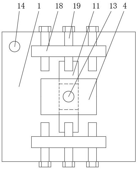
[0045] Such as figure 1 and 2 As shown, on the basis of Embodiment 1, the upper part of the support seat 1 has two adjustment seats 18, and the two adjustment seats 18 are respectively located at the left and right ends of the transverse rectangular guide hole 11, and the adjustment bolts 19 are threaded on the adjustment seats 18, and the adjustment bolts 19 is used to correspondingly push the left and right ends of the lateral adjustment block 4 to realize the lateral movement adjustment of the lateral adjustment block 4, and the adjustment bolt 19 can be adjusted by a socket wrench.

[0046] Specifically, three adjusting bolts 19 are arranged on each adjusting seat 18 , and one of the three adjusting bolts 19 at both ends is aligned with the middle of the left and right ends of the transverse adjusting block 4 .

Embodiment 3

[0048] Such as figure 1 , 7 As shown in and 8, on the basis of Embodiment 2, the top surface of the support seat 1 is provided with a long arc bottom groove 20, and the arc bottom groove 20 is parallel to the horizontal rectangular guide hole 11, and the horizontal rectangular guide hole 11 Both the front and rear ends have circular arc bottom grooves 20, specifically two circular arc bottom grooves 20 are arranged at the front and rear ends of the transverse rectangular guide hole 11, and the bottom surface of the horizontal adjustment block 4 is correspondingly provided with a strip-shaped circular arc top groove 21. Some balls 22 are installed in the bottom groove 20, and the balls 22 are steel balls 22. The arc top groove 21 covers and is arranged on the top of each ball 22, and each ball 22 is covered with a skeleton (not shown in the figure), and the skeleton holds each ball. 22 are separated, and the lateral adjustment block 4 is adjusted laterally on the upper surface...


PUM


Abstract

The invention relates to the technical field of pipeline welding, in particular to a supporting and adjusting structure for pipeline butting and welding and a use method thereof. Semicircular slots are formed in the bottom of a supporting seat; the tops of supporting rods are provided with mounting balls; the mounting balls are mounted in the semicircular slots; pressing blocks are provided with through holes; the inner surfaces of the through holes are spherical surfaces; the pressing blocks are arranged at the lower half parts of the mounting balls through the through holes in a sleeving manner; the pressing blocks press the mounting balls into the semicircular slots; the supporting rods can swing relative to the supporting seat for adjustment through the mounting balls; the supporting seat is provided with a transverse rectangular guide hole; the bottom of a transverse adjustment block is provided with a guide block; the guide block is located in the transverse rectangular guide hole and is matched with the transverse rectangular guide hole; the transverse adjustment block is provided with a vertical through hole; an adjustment screw rod passes through the vertical through holeand is in threaded connection with an adjustment sleeve; the adjustment sleeve is rotated to control the adjustment screw rod to vertically move relative to the supporting seat; and the bottoms of thesupporting rods are connected with steel wire ropes to hang a pipeline below the supporting seat. The end parts of two pipelines can be conveniently and quickly adjusted to be aligned. The adjustmentprocess is high in efficiency and low in labor intensity.

Description

technical field [0001] The invention relates to the technical field of pipeline welding, in particular to a support adjustment structure for butt welding of pipelines and an application method thereof. Background technique [0002] On-site pipeline construction operations often involve the butt welding of a large number of pipelines. When the welding base pipeline is supported in the air by the support foundation, it is necessary to support the pipeline to be butt welded stably and reliably at the same height, and to ensure that the pipeline to be welded Only by aligning the ends of the welded base pipes with the ends of the welded foundation pipes can the butt welding quality of the two be guaranteed. The existing hoisting equipment can be used to suspend the pipes to be butt welded in the air, but it is difficult to control the alignment of the ends of the two , and the cost of using existing hoisting equipment is high, and in the process of aligning the ends of the two, w...

Claims


Application Information

Patent Timeline
Patent Type & Authority Patents(China)
IPC IPC(8): B23K37/053B23K101/06
CPCB23K37/053
Inventor 陈意廖晓涛高志惠
Owner CHINA MCC5 GROUP CORP
Why Eureka
Try Eureka